|
T1154 Transmitter Lancaster Bomber
Transmitter
Radio Equipment 1154 Manual with
Circuit.
TRANSMITTERS, Types T1154, A, B, C, D,
E, F, H, I, K, L, M, N
T1154A, T1154B, T1154C, T1154D, T1154E, T1154F, T1154H,
T1154I, T1154K, T1154L, T1154M, T1154N
|
|
Circuit Diagram, Service
Manual, Service
Information, Schematic Diagrams and Manuals |
|
For Repairing, Restoration and
Servicing of Vintage and Modern Electronic Equipment |
|
Manual and
Circuit
Plus Additional Articles
available as a Download
Details Below
Click Here
|
|
Circuits
& Manuals
Military,
Radio, TV,
Amateur & Marine
World Wide Service
For
Lists Click Here
|
|
Use R/H scroll Bar
More information
below
Radio's For Sale
Click Here
Military and
Broadcast
Radio Ads Click
Here |
|
Military Radio Home
Click
Here If no Index to the left
|
T1154
Transmitter
Types T.1154, T.1154A, B, C, D, E, F, H,
I, K, L, M, N
T1154A, T1154B, T1154C, T1154D, T1154E, T1154F, T1154H, T1154I, T1154K,
T1154L, T1154M, T1154N
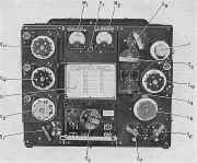
The 1154 transmitter was fitted to
the Lancaster bomber, motor torpedo boats and also used as a ground
station.
Many are still around in collectors hands and operational as is
the one pictured.
The frequency coverage is 5.5mc/s-1.5mc/s and
500kc/s-200kc/s in three ranges, blue, red, yellow.
The power output is
40-70 watts CW, 10-17.5 watts on RT "speech" and MCW.
The
aircraft version had an aluminum case for obvious reasons where as the
marine version had a steel case.
The weight of this unit is 46 lb 10 oz.
Percentage Modulation 70 per cent.
Class C, with suppressor grid modulation on M.C.W. and R/T.
Microphone Carbon granule, or electro-magnetic with sub-modulator
A.1134 or A.1134A.
Master Oscillator; sidetone and modulator; two indirectly-heated triodes,
VTIO5.
Power amplifier, two directly-heated pentodes. VT 104.
Power Input from 12 or 24-V. rotary transformers, supplied from aircraft system in airborne installations.
Or from a.c. mains via a
rectifier 1,200 volts, 200 mA. H.T.; 6 volts, 4 amps. L.T.; 6 volts
2.5amps keying relay, (approx. 280 watts total).
|
|
|
|
Additional information on the
Wireless Set 1154 Transmitter
Kindly
supplied by Bob Fairman.
The Lancaster was not the only
aircraft in which this equipment was installed.
They were used extensively
in aircraft of all types in the RAF during and after WW2.
I used them
during the whole of my time in the RAF from 1949 to 1957 and they
continued in use for some years after that.
During that time rumour had it
that in a storage depot 'somewhere in England' there was a warehouse
stacked to the rafters with unused replacement sets, which explained why
they had not been superseded by radios of greater power which would have
been a boon to us ops on long range Transport Command. |
Manual and
Circuit
Plus Additional Articles
available as a Download
Details Below
Click Here |
TRANSMITTERS, Types T.1154, T.1154A, B, C, D, E, F, H,
I, K, L, M, N
T1154A, T1154B, T1154C, T1154D, T1154E, T1154F, T1154H, T1154I, T1154K,
T1154L, T1154M, T1154N
Transmitters of the T.1154 series were designed primarily for installation in aircraft, to provide air-to-ground or air-to-air communication by
W/T, and in all but two versions by .R /T as well.
Series L, however, was intended for installation in
high-speed launches, and series D and E were introduced for mobile ground stations. Normally all these transmitters
were used with receivers of the R.1155 series.
Frequency coverage
Altogether there were thirteen production varieties of the T. 1154, the principal differences between them concerning frequency coverage and the provision or absence of R/T facilities. Component variations in the drive and output units, modifications of the “click-stop” mechanism for rapid selection of pre-set frequencies, and the use of steel or aluminium cases account for further versions.
Table 1 enumerates the different types of transmitter and their frequency ranges. The colours stated in the table are those of the tuning controls for the ranges concerned.
Frequency coverage of transmitters T.1154
T.1154, *T.l154A, T.1154B, T.1154J, T.l154N
Range 1 (HF.), BLUE 10 Mc/s to 5.5 Mc/s
Range 2 (H.F.), RED 5.5 Mc/s to 3.0 Mc/s
Range 3 (M.F.), YELLOW 500 kc/s to 200 kc/s
T.1154C, T.1154F, ~T.1154H, T.1154K, T.l154M
Range 1 (H.F.), BLUE 16.7 Mc/s to 8.7 Mc/s
Range 2 (H.F.), BLUE 8.7 Mc/s to 4.5 Mc/s
Range 3 (H.F.), RED 4.5 Mc/s to 2.35 Mc/s
Range 4 (M.F.) YELLOW 500 kc/s to 200 kc/s
T.1154D, *T.1154E
Range 1 (H.F.), BLUE 8 Mc/s to 4.5 Mc/s
Range 2 (H.F.), RED 4.5 Mc/s to 2.5 Mc/s
Range 3 (M.F.), YELLOW 500 kc/s to 200 kc/s
T.1134L
Range 2 (H.F.), RED 5.5 Mc/s to 3 Mc/s
Range 2A (H.F.), BLUE 3 Mc/s to l.5 Mc/s
Range 3 (M.F.), YELLOW 500 kc/s to 200 kc/s
*Note._Transrnitters marked with an asterisk provide C.W. and M.C.W. only. All others are for C.W., M.C.W., and RT.
In all transmitters with three frequency ranges there are separate sets of tuning controls for each range, identified by colours as in the foregoing table. Series C, F, H, K, and M, however, use the same set of controls, coloured blue, for the two higher
H.F. ranges.
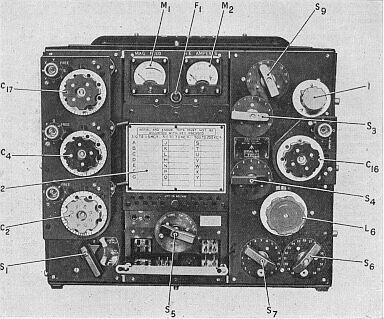
Pre-set frequency selection
The click-stop mechanism is arranged so that the tuning controls click into and are rigidly held in the correct position for pre-set frequencies.
With the Multi-click system all the chosen frequencies are selected in turn as the tuning dials are rotated, and the operator sees which one is engaged at any moment by means of lettered tabs coming into view behind an aperture.
The mechanism can be released to allow free rotation of the dials when setting up frequencies which have not been pre-selected.
The Uni-click mechanism on the other hand allows one click-stop to be brought into use at a time, the stop required being selected by turning a selector knob to the appropriate position on a lettered dial.
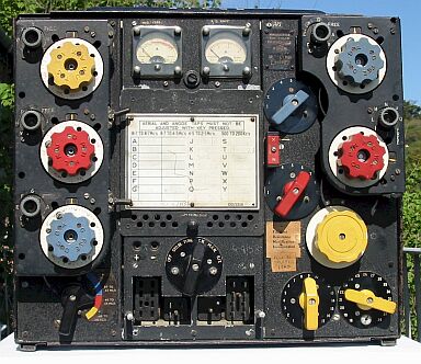
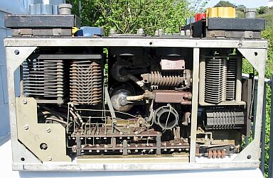
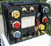
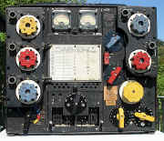
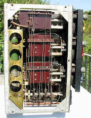
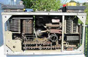
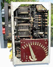
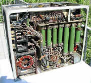
Pictured at right are various views
of my 1154 some showing the internal wiring.
Clicking on the images will
produce a larger view, please use your browser back button to return to
this page. |
|
|
|
|
|
|
|
|
Manual and
Circuit
Plus Additional Articles
available as a Download
Details Below
Click Here |
|
|
The
Wireless Set T1154 Transmitter
T1154A, T1154B, T1154C, T1154D, T1154E, T1154F, T1154H, T1154I, T1154K,
T1154L, T1154M, T1154N
Manuals are Available
Worldwide as a Download.
The Wireless Set
T1154 manual AP2548A contains 66 A4 pages including Circuits
Component lists and Layouts.
Plus 12 pages of Additional Articles if
required.
Manual 66 A4 pages worldwide : -Additional Articles 12 A4
pages worldwide : -
Special Offer Manual 66 pages and
Additional Articles 12 pages Total 78 pages.
( For all Payment Options )
( Please Click the Payment Links Below )
Details of Additional Service Articles available Below
Click Here |
|
We do all we can to provide
the very best that is available for you.
But in the unlikely event that any data should not be as you expected.
A refund is always available. Kind Regards Allen and Alanna. |
|
Manuals are Available
Worldwide as
a Download
Thank you for your interest. Allen
and Alanna G0RIT
Should you wish to purchase
 For Prices Payment Options and Delivery
Details
For Prices Payment Options and Delivery
Details
Manual Only
For Prices Payment Options and Delivery
Details
Additional Articles Only
For Prices Payment Options and Delivery
Details
Special Offer Manual and Additional
Articles


|
|
The T1154
Additional Articles 12 pages. |
The R.A.F. T.1154 Transmitter General
Notes
T9 with the T.1154 Simple Modifications
Some T.1154 Modifications Better Phone Quality and Improved Aerial
Coupling
About the T.1154 General Arrangement Modification and Operation
|
|
We do all we can to provide
the very best that is available for you.
But in the unlikely event that any data should not be as you expected.
A refund is always available. Kind Regards Allen and Alanna. |
|
Manuals are Available
Worldwide as
a Download
Thank you for your interest. Allen
and Alanna G0RIT
Should you wish to purchase
For Prices Payment Options and Delivery
Details
Manual Only
For Prices Payment Options and Delivery
Details
Additional Articles Only
For Prices Payment Options and Delivery
Details
Special Offer Manual and Additional
Articles
|
|