|
Marconi 1475 R1475
Type RG 44 Receiver AP2883G
|
|
Circuit Diagram, Service
Manual, Service
Information, Schematic Diagrams and Manuals |
|
For Repairing, Restoration and
Servicing of Vintage and Modern Electronic Equipment |
|
Manual and
Circuit
Available as a Download
Details Below
Click Here
|
|
Circuits
& Manuals
Military,
Radio, TV,
Amateur & Marine
World Wide Service
For
Lists Click Here
|
|
Use R/H scroll Bar
More information
below
Radio's For Sale
Click Here
Military and
Broadcast
Radio Ads Click
Here |
|
Military Radio Home
Click
Here If no Index to the left
|
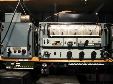
Receiver 1475 Type R1475 RG.44.
Marconi High-Discrimination
Communication RG44 AP2883G
This receiver with its
associated power supply unit was a piece of equipment of exceptionally
high performance in sensitivity, selectivity and frequency stability.
It
incorporated the then most recent advances in electrical and mechanical
design techniques, it was suitable for operation from either AC mains or
battery.
The receiver used a super-heterodyne circuit with twelve valves
and a visual tuning indicator which , in conjunction with the new type of
greatly extended tuning scale, permitted accurate tuning to within an
audible beat note of any given frequency in the band of 2 to 20 Mc/s. |
|
In appearance this equipment departed
from the conventional lines, since the special tuning unit and scale
occupied a considerable portion of the front panel.
Tuning adjustments
were effected by means of two large knurled thumb controls, placed for
convenience in operating at one end of the tuning drum, at the other end
is the wave-change lever, all other controls were arranged in two rows
below this.
High-discrimination, direct-reading tuning scale
This
took the form of a drum on which the entire tuning scale is printed in
spiral form so that the developed length of the scale was nearly 30 feet.
It was graduated at 10kc/s intervals throughout the entire band, the scale
separation between marks being 3/16" up to 11.3 Mc/s and more than
1/8" up to 20 Mc/s. |
|
As the drum was rotated by means of
the knurled thumb wheel, moving pointers indicate on which spiral the
frequency required was to be read. A static horizontal scale associated
with the pointers indicated the frequency in whole numbers of Mc/s.
Frequency-calibration check points were clearly marked at 600 kc/s
intervals on the drum.
Frequency Calibration-scale checking
Facilities were provided in the receiver for checking the accuracy of the
scale calibration to very fine limits and for correcting the calibration
when necessary.
The harmonics of the crystal controlled 2nd heterodyne
oscillator were fed back to the anode circuit of the RF amplifier valve,
which was itself switched off so that all other carriers which might cause
confusion are excluded from the mixer and subsequent stages. |
Manual and
Circuit
available as a Download
Details Below
Click Here |
By this means whistles were produced
at 600 kc/s intervals throughout the tuning range and the positions at
which they should be heard were marked on the rotating scale.
If however
the carrier whistles do not correspond to the scale check points, they can
be made to do so by means of the "Scale Trimmer" control. This
control was in effect an inductance trimmer, by means of which a constant
percentage control of the1st heterodyne oscillator was obtained. In this
way changes due to drift can be corrected through -out the whole of the
bands and constant re-checking was therefore un-necessary. |
|
Guard-Frequency
In addition
to the precision tuning-adjustment facility a further innovation was
introduced in this receiver in the form of a device which enables
reception on a fixed frequency between 2 to 7.5 Mc/s,(150 to 40m), (e.g.
Guard Frequency) to be carried on
simultaneously with the reception of signals on any other frequency (or on
the same frequency).
Thus on one receiver a double watch could be kept.
This dual channel effect was obtained by the use of a second mixer valve
which performed the combined functions of an auxiliary mixer and auxiliary
oscillator.
The oscillator was controlled by a standard plug-in crystal,
and the HF circuit associated with this channel takes the form of a unit
which is plugged into the front of the set. |
Manual and
Circuit
available as a Download
Details Below
Click Here |
When the guard- frequency valve was
switched on, a signal on that frequency breaks through, irrespective of
the frequency to which the main tuning controls were set.
Frequency
Coverage
2 to 20 Mc/s (150 to 15m) in 4 Bands.
Band1 :- 2
to 3.6 Mc/s.
Band 2 :- 3.6 to 6.4 Mc/s.
Band 3 :- 6.4
to 11.3 Mc/s.
Band 4 :- 11.3 to 20 Mc/s.
Output
To suit 60, 150, or 2000 ohm resistance telephones adjustable by tapped
output transformer.
600 ohm balanced and un-balanced outputs, high or low
level.
Selectivity
Three switch-selected bandwidths available; 5 kc/s,1200
c/s and 300 c/s, including LF filters.
Power Supply Unit
200/250volts AC (50 c/s).
Consumption
60 watts or 4 amps from 12
volt accumulator. Appropriate tapping's available on transformer.
Output
HT 260 volts DC, 65mA. LT 12.6 volts AC, 2.0 Amps.
The receivers weight
40
lbs -18 3 kg. The supply unit weighs 25 lbs - 11.3kg. |
|
We supply two
Manuals for the The Receiver
R1475 1475 RG44.
Manual AP2883G containing 59 A4 pages including Circuits,
Component lists and Alignment.
Manual T1980
which contains 74 A4 pages including Circuits, Component lists,
Alignment and seven pages of modification notes.
Total of 133 Pages.
Manuals are Available
Worldwide as
a Download.
Manual 133 A4 pages worldwide
( For all Payment Options )
( Please Click the Payment Links Below ) |
|
We do all we can to provide
the very best that is available for you.
But in the unlikely event that any data should not be as you expected.
A refund is always available. Kind Regards Allen and Alanna. |
|