|
WS 19 Set High Power Amplifier
No 2 Mk 1 2 & 3
WS19
Mk1 Mk11 Mk 111 Mk I MK II Mk III
|
| Five Wireless Set No 19 WS 19 Variometer Aerial Tuner Units
For Sale Please
Click
Here |
|
Circuit Diagram, Service
Manual, Service
Information, Schematic Diagrams and Manuals |
|
For Repairing, Restoration and
Servicing of Vintage and Modern Electronic Equipment |
|
Operating and Service
Information Including
The Circuit Diagram
Available Details Below
As a Download
Click Here
|
|
Circuits
& Manuals
Military,
Radio, TV,
Amateur & Marine
World Wide Service
For
Lists Click Here
|
|
Use R/H scroll Bar
More information
below
Radio's For Sale
Click Here
Military and
Broadcast
Radio Ads Click
Here |
|
Military Radio Home
Click
Here If no Index to the left
|
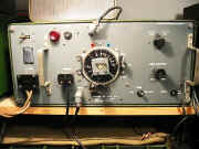
The RF amplifier No 2
Designed to
amplify the modulated RF output from the Wireless Set No 19
and thus to increase the range of the latter.
It employs two or four ATS
25 valves in parallel which operate under Class A conditions.
On RT
and MCW send / receive switching is carried out in the normal way from the
19 set, when sending CW however a separate S / R switch
on the amplifier unit is used.
The 19 set variometer is replaced by
Inductance Aerial Tuning No1, which tunes the aerial to a quarter
wavelength.
|
|
When the amplifier is switched off the
19 set works normally without any reconnection.
The amplifier tunes
from 2.1 Mc/s - 7.5 Mc/s in two bands and over this frequency range
full gain is obtained.
Operation between 2 & 2,1 Mc/s and between 7.5
and 8 Mc/s is possible on any 19 set but full gain is not generally
obtained.
Power Supply : -
Power is derived
from the 12 volt accumulator which supplies heater current for the two or
four ATS 25 valves connected in series - parallel, as well as input to a
rotary transformer contained in the unit.
|
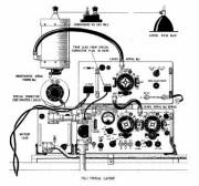 |
The rotary transformer which
supplies HT to anodes and screens has an output of
approximately 600v at 240 mA.
Accumulator current consumption for the
amplifier alone is about 24 amps on send and 2.5 amps on receive.
All Mk 2
amplifiers are fitted with a cooling fan and they may be run
continuously on send.
Mk 1 amplifiers without fans must not be run
continuously for more than 15 mins in each hour. |
Operating and Service
Information Including
The Circuit Diagram
Available Details Below
As a Download
Click Here |
WS 19 Set High Power Amplifier
No 2 Mk 1 2 & 3
WS19
Mk1 Mk11 Mk 111 Mk I MK II Mk III
Manuals are Available
Worldwide as
a Download.
Manual 24 A4 pages worldwide.
( For all Payment Options )
( Please Click the Payment Links Below ) |
|
We do all we can to provide
the very best that is available for you.
But in the unlikely event that any data should not be as you expected.
A refund is always available. Kind Regards Allen and Alanna. |
|