|
Wireless Set No 38 Mk11 Mk11*
Mk
11 Mk 11* MkII MkII* Mk II Mk II*
WS No 38 Mk2 Mk2* Mk 2 Mk
2* Mark Two Walkie Talkie
|
|
Circuit Diagram, Service
Manual, Service
Information, Schematic Diagrams and Manuals |
|
For Repairing, Restoration and
Servicing of Vintage and Modern Electronic Equipment |
|
Manual and
Circuit
available
Details Below
As a Download
Click Here
|
|
Circuits
& Manuals
Military,
Radio, TV,
Amateur & Marine
World Wide Service
For
Lists Click Here
|
|
Use R/H scroll Bar
More information
below
Radio's For Sale
Click Here
Military and
Broadcast
Radio Ads Click
Here |
|
Military Radio Home
Click
Here If no Index to the left
|
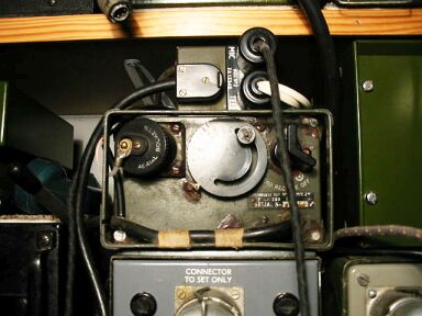
The Wireless Set No 38, Mk2 or Mk2*
The set
is a light man-pack RT set, simple to operate and carried in three
portions
The set itself, the signals satchel, and the canvas aerial case
containing rod aerials.
It has a frequency band from 7.4 Mc/s to 9 Mc/s
and an effective range up to half-a-mile with the 4ft rod aerial
and up to
two miles with the 12ft rod.
The complete station , including spare
battery, weighs 27.5 lbs. |
|
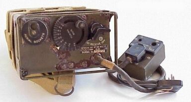
The Mk2 and Mk2* models are
externally similar except that the rubber test button and aerial current
indicating lamp
provided on the Mk 2 are not present in the
Mk2*
Internally the Mk2 oscillator send-receive tracking circuit is
modified to the Mk 2* circuit to produce a reduced
difference
between send and receive frequencies with change of temperature.
|
See Also WS 38 AFV
Click Here
|
Rod aerials :-
Four aerial
rods F sections are provided, one being spare.
When using a 4ft rod
aerial, place the thinnest section in the small aerial socket.
When using
a 12ft aerial, fit three sections together and place
the thickest section in the large aerial socket.
The aerial circuit is
automatically tuned either for a 12ft rod in the large socket or a 4ft rod
in the small socket;
an 8ft rod should not normally be employed.
|
|
Ground aerials :-
When in close
contact with the enemy, the rod aerial is much too conspicuous and
therefore
a ground aerial should be used.
For most wireless working it is
just as satisfactory as a rod aerial.
A ground aerial consists of a length
of insulated wire laid out in a straight line,
one end being attached to
the adapter plug which should be fitted into the large aerial socket.
The
other end is left free and pointing if possible, in the direction of the
distant station
or as a second best, in the opposite direction.
|
Manual and
Circuit
available
Details Below
As a Download
Click Here
|
No earth connection is
necessary and the set can be on the ground or at the bottom of a trench,
or in the usual carrying position, or on the move with the wire
trailing along the ground.
Power Supply :-
The set requires
150 volt HT and 3 volt LT supply, this may be supplied by a dry battery
( batteries, dry, HT,/LT. No 1 or 2 )
The HT current consumption is 16 mA on
send and 9 mA on receive and the LT current consumption
0.48A on send and
0.24A on receive.
|

|
The power for the set can also
be supplied by Power Supply Unit No 5, this is used for special
operations in order to conserve battle batteries, or in an emergency when
batteries are not available.
The Power Supply Unit No 5 has a 6 volt
accumulator, vibrator and a hand driven charging generator.
The unit is
arranged for transport as a man-pack.
In the course
of WW2 similar and more powerful man-pack radios were developed for the
army,
while towards 1945 trials were carried out with fully tropicalised
miniature sets.
After 1947 the set was replaced by the wireless set No 88
( on which development had started in 1944. |
|
The Information Consists
of the Following
Service Information and Operating Instructions
Circuit diagram
Components and values
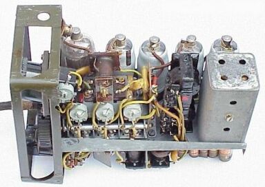
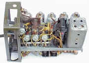
Top chassis view
Bottom Chassis view
Valve Base Connections
Plus and Sockets
Working Instructions
Alignment
Maintenance
How to Connect for retransmission with 19 Set
Fault Finding
How to make a Mains Power Supply
|
Manual and
Circuit
available
Details Below
As a Download
Click Here
|
Wireless Set No 38 Mk11 Mk11* Mk 11 Mk 11* MkII MkII* Mk II Mk II*
WS No 38 Mk2 Mk2* Mk 2 Mk 2* Mark Two Walkie Talkie
Manuals are Available
Worldwide as
a Download.
Manual Wireless Set No 38 71 A4 pages
including the Circuit, Layouts & Alignment.
Available worldwide.
( For all Payment Options )
( Please Click the Payment Links Below ) |
|
We do all we can to provide
the very best that is available for you.
But in the unlikely event that any data should not be as you expected.
A refund is always available. Kind Regards Allen and Alanna. |
|