|
Circuit Diagram, Service
Manual, Service
Information, Schematic Diagrams and Manuals |
|
For Repairing, Restoration and
Servicing of Vintage and Modern Electronic Equipment |
|
Manual
Circuit and
Operation Instructions
available
Details Below
As a Download
Click Here
|
|
Circuits
& Manuals
Military,
Radio, TV,
Amateur & Marine
World Wide Service
For
Lists Click Here
|
|
Use R/H scroll Bar
More information
below
Radio's For Sale
Click Here
Military and
Broadcast
Radio Ads Click
Here |
|
Military Radio Home
Click
Here If no Index to the left
|
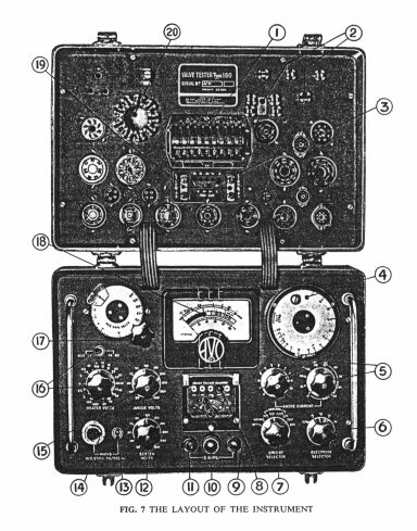
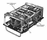
AVO CT160 Valve Tester
The instrument will
(I) Check heater continuity.
(2) Measure insulation between electrodes with valve cold.
(3) Measure insulation between electrodes with valve hot.
(4) Measure cathode/heater insulation (for indirectly heated valves).
(5) Rapidly indicate whether a valve is good or bad, use being made of a coloured replace/good scale with mutual conductance as the operative parameter.
(6) Measure the mutual conductance (slope) of a valve, the applied incremental grid voltage being inversely proportional to the “slope” of the valve.
(7) Measure anode current in single and multi-anode valves.
(8) Produce sufficient data to enable static characteristic curves to be plotted on graph paper.
(9) Check rectifiers and diodes under load conditions.
(10) Measure gas current, limited to l00~A.
(11) Measure Screen Current.
The instrument is fitted with an automatic aural and visual warning device which operates if certain circuits within the instrument are inadvertently overloaded by the operator, or if a short occurs upon a valve under test.
The use of specially designed circuits, virtually eliminate the possibility of the valve under test bursting into spurious oscillation.
Power Requirements
The instrument will operate from the following 50 - 500c/s AC supplies:
- 105 - 120V, 175
- 250V. (Adjustment can be made at every 5V.)
Power Consumption
50 watts, maximum.
Physical Data
Weight: 24 lbs. (approx.)
Height: 10 inches
Depth: 11 1/2 inches
Width: 15 1/2 inches
Joint Services Designation
AVO Valve Tester CT16O.
|
|
|
|
|
Operating Instructions and Valve Data 51 Pages
AVO VALVE TESTER C.T.160 51 PAGES
Amendment Record
Abbreviated Working Instructions for A.P.61761 “AVO” Valve Tester CT. 160
Diagram of Standard Pin Connections
Diagram of Special Valve Holders
Valve Data for Army ‘A’ Series Valves
Valve Data for Joint Services ‘CV’ Series Valves
Valve Data for Naval ‘N’ Series Valves
Valve Data for Air Force ‘V’ Series Valves
Test Data for High Voltage Rectifiers
Service Equivalents of Civilian Types
|
|
The Manual Hand Book contains the following
: -
“AVO” VALVE TESTER C.T.160 51 PAGES
PART I
CHAPTER 1.
TECHNICAL DESCRIPTION
Introduction
Principles of operation
Basic Circuitry
The Valve Holder Panel
General Construction
Mains Supply
Circuit Diagram
Component List
CHAPTER 2.
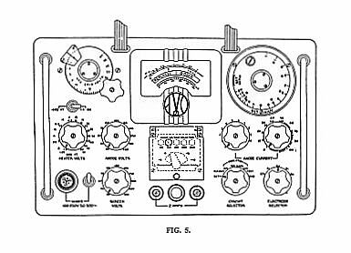
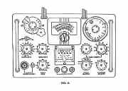
THE VALVE PANEL AND CONTROL UNIT
The Valve Panel and Selector Switch
Procedure for setting up Valve Base Connections
Provision for new Valve Bases
The Control Unit and its Function
14 The Mains Voltage Selector
The Circuit Selector
The Electrode Selector
The Heater Voltage Switches
The Anode and Screen Voltage Switches
The Anode Current Controls
The Negative Grid Volts Control
The Set mA/V Control
CHAPTER 3.
PERATING INSTRUCTIONS AND
GENERAL PROCEDURE FOR TESTING
A VALVE
The connection of the instrument to a supply voltage
Final setting of Mains Voltage Selector Panel
Insulation checks with the valve cold
Insulation checks with the valve hot
Cathode to Heater insulation check
Determination of valve condition from Static Characteristic Data
To check relative goodness of valve in conjunction with coloured comparison
scale
(a) Using recommended anode current
(b) Using recommended negative grid voltage
To check valve by direct reading of mutual conductance (mA/V)
(a) Using recommended anode current
(b) Using recommended negative grid voltage
To check valves having a mutual conductance less than ImA/V
Measurement of Grid Current
Checking Power Rectifiers
Checking Signal Diodes
Instructions for testing specific valve types
Multiple Diodes and Rectifiers (D, DD, DDD, R, RR)
Diodes and Rectifiers combined with other electrode assemblies
CDT, DDT,
DP, DDP, DTP)
Double Triodes and Double Pentodes (TT, PP)
Frequency Changers (H, TH, 0, TP)
The use of the Links on the Valve Panel of the instrument
Checking Tuning indicators (TI)
Checking Gasfilled Rectifiers (OR)
Checking Cold Cathode Rectifiers (CCR)
PART 2
CHAPTER 1.
CALIBRATION AND MAINTENANCE OF THE INSTRUMENT
Instruments to be employed
500.c/s AC. Supply operation and its relation to Servicing
To Check Accuracy of Instrument
To obtain standard figures for a valve using D.C. Supplies
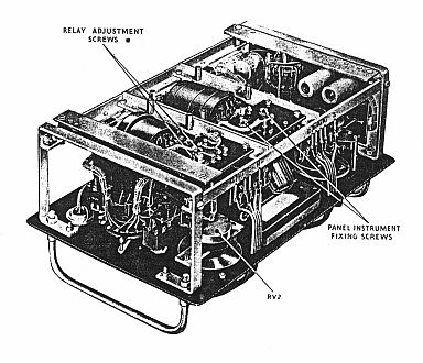
Mechanical features
Removal of the instrument from its case
Simple faults
Relay operates and fails to clear
Voltage Checks with no valve under test
Heater Voltages
Anode Voltages
Screen Voltages
Calibration of the Instrument
Checking the Set mA/V Control
Checking the SET Indication
Ia Calibration Check
The Indicating Meter
Adjustment of Protective Relay
Servicing the Valve Holder Panel
Removal and replacement of knobs and setting of knob skirts
Setting the mA/V Dial
Plus AVO Valve Data Manual 1968 230 Pages
|
Manual
Circuit and
Operation Instructions
available
Details Below
As a Download
Click Here |
|
Manual
Circuit and
Operation Instructions
available
Details Below
As a Download
Click Here |
AVO
CT160 Valve Tester
Manuals are Available
Worldwide as
a Download.
Operating Instructions 51 pages and the Hand
Book 51 pages Total 102 pages
Including the Circuits with component values and
Layouts
Plus the AVO Valve Data Manual 1968 230 Pages
Total 332 Pages
Manual 332 A4 pages worldwide
( For all Payment Options )
( Please Click the Payment Links Below )
|
|
We do all we can to provide
the very best that is available for you.
But in the unlikely event that any data should not be as you expected.
A refund is always available. Kind Regards Allen and Alanna. |
|