|
BBC-224 BC-348 BC-224-E BC-224-F BC-224-G
BC-224-H
BC-224-K BC-224-L BC-348-E BC-348-H
BC-348-J
BC-348-K BC-348-L BC-348-M BC-348-N BC-348-O
BC-348-P BC-348-Q BC-348-R BC-348-S Radio Receiver
|
|
Circuit Diagram, Service
Manual, Service
Information, Schematic Diagrams and Manuals |
|
For Repairing, Restoration and
Servicing of Vintage and Modern Electronic Equipment |
|
Manual
Circuits and
Layouts Available
Plus Additional Articles
Details Below
As a Download
Click Here
|
|
Circuits
& Manuals
Military,
Radio, TV,
Amateur & Marine
World Wide Service
For
Lists Click Here
|
|
Use R/H scroll Bar
More information
below
Radio's For Sale
Click Here
Military and
Broadcast
Radio Ads Click
Here |
|
Military Radio Home
Click
Here If no Index to the left
|
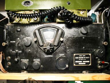
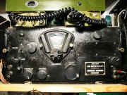
BC348
The B-348 is a compact American made
communications receiver, which was mass-produced during the war for the
U.S. Army Air Force.
The BC-348 series ran to several mark letters
during its long production history.
Although the outside appearances
were similar, internally there were considerable divergences, particularly
with the later models.
The basic common specification was of a superhet
having two r.f. stages, frequency-changer, three i.f. stages, detector /
a.g.c. and output stage. |
|
There was no intermediate a.f
amplifier between detector and output.
The frequency-changer stage in the
earlier marks consisted of separate mixer and local oscillator valves,
later altered to a single-valve configuration.
The early marks had a b.f.o.
combined with the 2nd i.f. amplifier, whilst the later types had it
combined with the detector / a.g.c. valve.
The Frequency Coverage was
the same for all marks:
200-500 Hz
1.5-3.5 MHz
3.5-6 MHz
6-9.5 MHz
9.5-13.5 MHz
13.5-18 MHz. |
|
The Power Source being the
aircraft 24v service battery, the valve heaters were arranged in
series-parallel to present a nominal 25.2v load.
The h.t. was supplied by
a dynamotor rated at 28v input and approximately 235v output at 75mA.
Why
28v you may ask ? well a lead-acid accumulator of nominally 24v (12
two-volt cells) gives 26.4v when fully charged, (2.2v per cell). However,
when on charge the terminal voltage will be of the order of 28v, hence the
input rating of the dynamotor. |
Manual
Circuits and
Layouts Available
Plus Additional Articles
Details Below
As a Download
Click Here |
Resistors were also placed in the
heater circuit to reduce the voltage, as the battery was expected
to be on charge throughout operational flights.
Similarly a nominal 12v
battery gives 13.2v fully charged and a terminal voltage of around 14v on
charge.
Another series of receivers numbered BC-224 was in concurrent
production, these models being identical with the BC-348 except for the
power source a 12.6v battery. |
|
The Manual Contains similar
information to the
Following depending on model
On the BC348 Name Plate there
will be a letter of the alphabet please quote this with your order
TABLE OF CONTENTS
GENERAL DESCRIPTION
General
Component Units
Cabinet
Chassis
Dial and Mask Assembly
Dynamotor
I-F Transformers, Crystal Filter, C.W Oscillator
Mounting
Panel
Plug
R-F and Oscillator Units
INSTALLATION AND ADJUSTMENT
Initial Procedure
Unpacking
Inspection
Installation
Mounting
Electrical Connections
Elimination of Electrical Interference
Mounting the Receiver
Antenna and Ground Connections
Preparation for Use
Inspection
Controls
OPERATION
Procedure
Operating Test
Reception
MECHANICAL AND ELECTRICAL CHARACTERISTICS
Circuits
Frequency Range and Bands
Input Coupling
Radio Frequency Amplifier
First Detector
Heterodyne Oscillator
Intermediate Frequency Amplifier
C-W Oscillator
Crystal Band-Pass Filter
Second Detector
Output
Description
Constant Internal Receiver Noise
Dynamotor DM~28~(*)
MAINTENANCE
Inspection
Dynamotor Service and Maintenance
Removal from Chassis
Lubrication
Commutator
Bearings
Reassembly
Power Rating
Removal of Front Panel
Dial and Mask Assembly
Servicing the Dial and Mask Assembly
Removal
Disassembly
Dial Replacement
Stop Arm Replacement
Replacement of Dial and Mask Assembly
Dial Calibration
Removal of Antenna, R-F Detector and Oscillator Units
Trouble Location and Remedy
Quick Check
Sensitivity
Trouble Location and Correction Procedure
Equipment Required
Weak or No Signals on All Bands, Modulated Reception
Weak or No Signals on Any One Band, Modulated Reception
Weak or No Signals on All Bands-C-W Reception (Modulated Reception Normal)
Measurements with Test Set 1.56-A
Failure of Dial Lights
SUPPLEMENTARY DATA
General
TABLE OF REPLACEABLE PARTS
DRAWINGS
LIST OF ILLUSTRATIONS
Radio Receiver BC-348J
Radio Receiver BC-348-J, Tube Positions
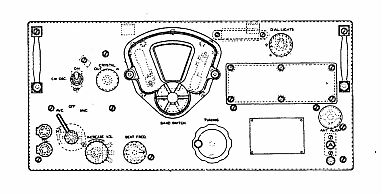
Radio Receiver BC-348-J, View of Front Panel
C-W Oscillator Switching
Crystal Filter Circuit
AVC Connections
MVC Connections
Dynamotor DM.28-J and Filter
Radio Receiver BC-348-J, Dial and Mask Assembly
Trouble Location and Correction Chart
Crystal Filter Coil
Socket Voltages
Location of Trimmer Capacitors
Radio Receiver BC.348-J, Front View
Radio Receiver BC-348-J, Rear View of Chassis
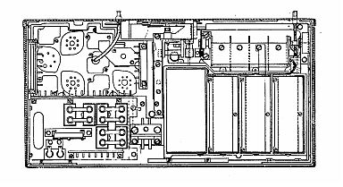
Radio Receiver BC-348-J, Top View of Chassis
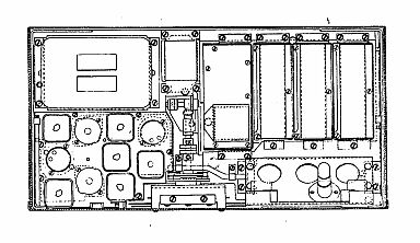
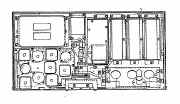
Radio Receiver BC-348-J, Bottom View of Chassis
Radio Receiver BC-348-J, Partial Bottom View
Mountings FT-154-J, FT.154-Q, and FF-154-AA with Plug Assemblies, Rear View
Radio Receiver BC-348-J, Front View of Cabinet
Antenna Unit
R-F Unit
Detector Unit
Oscillator Unit
I-F, C-W Oscillator and Crystal Coil Assemblies
Radio Receiver BC-348-J, Schematic Diagram
I-F Transformers, Wiring Diagram
Radio Receiver BC-348-J. Outline Dimensional Sketch
Mounting FT-154-J, Drilling Plan
Radio Receiver BC-348-J, Wiring Diagram of Chassis
Antenna, R.F, Detector and Oscillator Units, Wiring Diagram
Radio Receiver BC.348-J, Plug Connections
|

|
|

|
|
|
|
BC 348 BC348 BC-348 BC 224 BC224 BC-224
BC-224-E BC-224-F BC-224-G BC-224-H BC-224-K BC-224-L
BC-348-E BC-348-H BC-348-J BC-348-K BC-348-L BC-348-M BC-348-N
BC-348-O BC-348-P BC-348-Q BC-348-R BC-348-S Radio Receiver
Manuals are Available
Worldwide as
a Download.
On the BC-348 Name Plate there
will be a letter of the alphabet please quote this with your order.
All the text and diagrams are sharp
and clear, some of the photographic images on our original copies were
dark.
We will have duplicated them with other images wherever possible.
All data comes with a full refund option if not as expected : )
Manual including the Circuits with
Component lists and layouts between 70 & 98 A4 pages worldwide
( For all Payment Options )
( Please Click the Payment Links Below ) |
Additional Articles 27 Pages as follows : -
BC348 Modified
( Notes on adapting a useful receiver for amateur Operation )
The BC-348 Receiver
( Modifications and Improvements )
Modification Details for the BC-348 Part I
( Power Supply, Signal Frequency Circuit Alterations, Valve Changes,
Improving Audio Out, Adding Noise Limiter and S Meter,
Converter for 10 Meters, Fault Tracing Sequence )
Modification Details for the BC-348 Part II
( Further Circuit Data )
Modification Details for the BC-348 Part III
( Range Extension, Converter for 10 Meter
Operation, Alignment Details, Servicing Data, Voltage & Current Tables )
Improvements for the BC-348Q
( Noise Limiting, More Audio Output,
Controllable RF Gain )
Articles 27 A4 pages worldwide
BC 348 BC348 BC-348 BC 224 BC224 BC-224
BC-224-E BC-224-F BC-224-G BC-224-H BC-224-K BC-224-L
BC-348-E BC-348-H BC-348-J BC-348-K BC-348-L BC-348-M BC-348-N
BC-348-O BC-348-P BC-348-Q BC-348-R BC-348-S Radio Receiver
( For all Payment Options )
( Please Click the Payment Links Below ) |
|
We do all we can to provide
the very best that is available for you.
But in the unlikely event that any data should not be as you expected.
A refund is always available. Kind Regards Allen and Alanna. |
Manuals are Available Worldwide as
a Download
Thank you for your interest. Allen
and Alanna G0RIT
Should you wish to purchase
 |
Manual containing between 70 and 98 pages including the Circuits with Component lists and layouts.
On the BC-348 Name Plate there will be a letter of the alphabet
please quote this with your order
For Worldwide Payment Options and Delivery Details |
|
|
"Additional Articles 27 Pages"
For Worldwide Payment Options and Delivery Details |
|
|
"Special Offer Manual and Additional
Articles
" Saving over £7.50 "
For Worldwide Payment Options and Delivery Details |


|
|