|
ET4331 Transmitter High Power Communications
|
|
Circuit Diagram, Service
Manual, Service
Information, Schematic Diagrams and Manuals |
|
For Repairing, Restoration and
Servicing of Vintage and Modern Electronic Equipment |
|
Manual and
Circuit
available
Details Below
As a Download
Click Here
|
|
Circuits
& Manuals
Military,
Radio, TV,
Amateur & Marine
World Wide Service
For
Lists Click Here
|
|
Use R/H scroll Bar
More information
below
Radio's For Sale
Click Here
Military and
Broadcast
Radio Ads Click
Here |
|
Military Radio Home
Click
Here If no Index to the left
|
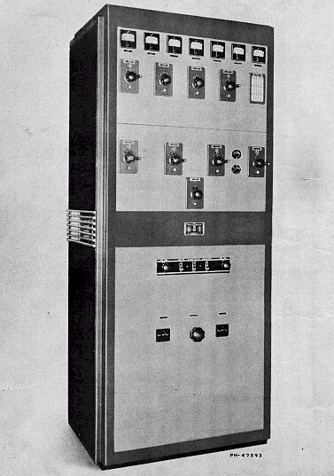
ET4331 High Power
Communications Transmitter.
TECHNICAL SUMMARY Main
Transmitter
ELECTRICAL CHARACTERISTICS
Frequency Range 3000 to 20,000 KC
Power Output
Telegraph 1300 watts
Telephone 1000 watts
Power Input
Telegraph (Max.) 4150 watts
Telephone (Max.) 5400 watts
Power Supply 1 ph. 220 v. 50/60 cycles
Tube Complement
Crystal Oscillator I RCA-802
Intermediate Power Amplifier 1 RCA-803
|
|
Power Amplifier 2 RCA-833-A
1st Audio Amplifier 1 RCA-5 3
2nd Audio Amplifier 4 RCA-2A3
Modulator 2 RCA-833-A
Rectifier 4 RCA-8 72-A/8 72
MECHANICAL SPECIFICATIONS
Height (Overall) 84½ inches
Length 361,4 inches
Depth (Overall) 27% 6 inches
Weight 1635 pounds
EQUIPMENT
The H-F Communications Transmitters described
are identified by the Ml designations, MI-7 162 and MI-7 162-A. The
MI-7 162 is less the coupling unit, while the MI-7
162-A is including the coupling unit. In all
other respects, the equipments are identical.
|
|
TECHNICAL SUMMARY Oscillator Unit
ELECTRICAL CHARACTERISTICS
Output Frequency 2 to 20 megacycles
Output Level, Buffer-Amplifier Sufficient to drive an RCA-80 7
Modulation Frequency 600 cycles
Frequency Deviation (maximum) ±500 cycles
Power Consumption 200 watts
Power Supply 11 5/2 30 volts, 50/60 cycles
Oscillator Filament Current 0.05 ampere d.c.
Amplifier and Tone Generator Filament
Voltage 6.3 volts a.c.
TUBE COMPLEMENT
Electron-Coupled Oscillator 2 RCA-3Q5-GT
Buffer-Amplifier 1 RCA-807
Tone Generator I RCA-6AB7, 1 RCA-6F6
Regulated Power Supply
2 RCA-5U4-G, 5 RCA-6Y6-G,
I. I RCA-1852, 2 RCA-VR-150/30
|
|
MECHANICAL SPECIFICATIONS
Dimensions Height, 66 9/16 in.; Width, 22 in.; Depth, 17 1/8 in.
Weight 275 pounds
TYPICAL PERFORMANCE DATA
Frequency Change
Line voltage change, ± 10 per cent
0.000 5 per cent
Temperature change, per degree Fahrenheit
0.000 7 per cent
Relative humidity change of 1 per cent
over the range of 30 to 95 at a dry bulb
temperature of 110 degrees F
0.000 3 per cent
Drift from cold start, first reading taken within 1
minute after applying power:
Frequency deviation at the end of the first
hour a negative drift of 100-400 cycles
(measured at 7 mc)
The Master Oscillator Equipment is
identified by the stock number MI- 19427-B and is
composed of the following major items:
1 Master Oscillator Unit (K-882006)
I Transmission Line Cable, 50 feet long (K-881380-1)
I Instruction Book IB-300 14-1
|
|
|
The Manual is complete except for the Oscillator
regulated power supply circuit |
The Manual contains the following
:-
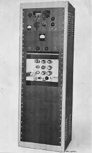
1 - Type ET-4 331 High-Frequency Transmitter
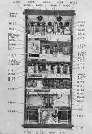
2 - Transmitter. (Rear View)
3 - Transmitter (Side Elevations)
4 - Transmitter (Schematic T-61 1 5 11)
5 - Transmitter (Connections TT-6 1 1654)
6 - Transmitter Coupling Unit (Connections M-429639)
7 - Transmitter (Outline M-4 18357)
8 - Crystal Oscillator (Dial B) (Calibration Curve S-85 1196)
9 - Intermediate Power Amplifier (Dial C) (Calibration Curve 5-851197)
40 - Power Amplifier (Dial F) (Calibration Curve 5-851198)
TECHNICAL SUMMARY
Electrical Characteristics
Tube Complement
Mechanical Specifications
Typical Performance Data
EQUIPMENT
DESCRIPTION
Construction
Circuits
INSTALLATION
Location
Assembly
Wiring
Tuning
Frequency Stability
OPERATION
MAINTENANCE
TYPICAL CALIBRATION
PARTS LIST
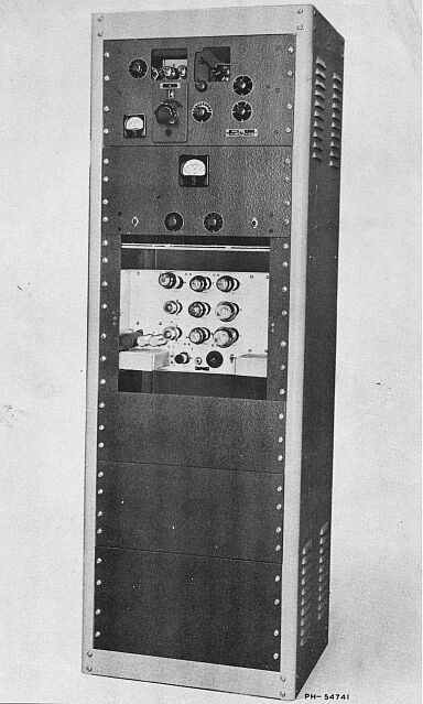
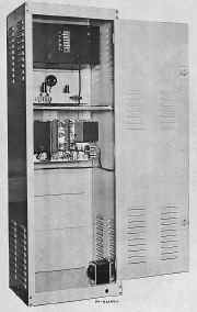
1 - MI-I 942 7-B Master Oscillator (Front Oblique View, Access Covers in Place)
2 - Oscillator Controls “B” and “C” (Typical Calibration, S-852928—Sub 0)
3 - Oscillator Controls “D” and “E” (Typical Calibration, S-85292 7—Sub 0)
4 - Oscillator Controls “F” and “Output Circuit” (Typical Calibration, S-852926----Sub
0)
5 - MI-1 942 7-B Master Oscillator (Front Oblique View, Access Covers Removed)
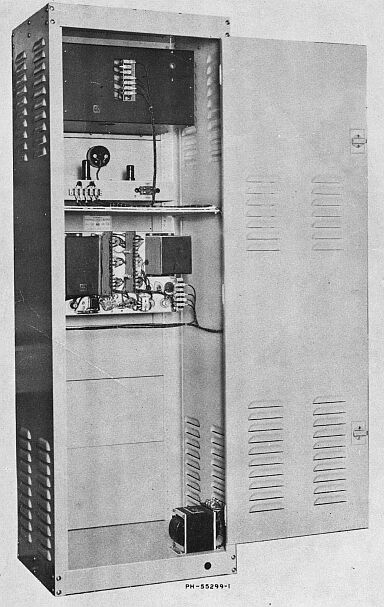
6 - MI- 19427-B Master Oscillator (Rear View, Access Door Open)
7 - Master Oscillator Chassis (Top View)
8 - Master Oscillator Chassis (Bottom View)
9 - Tone Generator Unit (Front View)
10 - Tone Generator Chassis (Bottom View)
I 1 - Regulated Power Supply Unit (Rear View)
12 - Master Oscillator Unit (Schematic, P-722222-Sub 1)
13 - Tone Generator Unit (Schematic, M-426986-Sub 2)
14 - Regulated Power Supply Unit (Schematic, P-72 199O-Sub 1) N/A
|
Manual and
Circuit
available
Details Below
As a Download
Click Here
|
|
The Manual is complete except for the Oscillator
regulated power supply circuit |
ET4331 Transmitter High Power Communications
Manuals are Available Worldwide as a
Download.
Manual including circuits 50 pages
Manual 50 A4 pages worldwide
( For all Payment Options )
( Please Click the Payment Links Below ) |
|
We do all we can to provide
the very best that is available for you.
But in the unlikely event that any data should not be as you expected.
A refund is always available. Kind Regards Allen and Alanna. |
|