|
Heathkit Mobile Transmitter HX-20
HX20
|
|
Circuit Diagram, Service
Manual, Service
Information, Schematic Diagrams and Manuals |
|
For Repairing, Restoration and
Servicing of Vintage and Modern Electronic Equipment |
|
Manual
with Circuit
Component Values &
Alignment
Details Below
As a Download
Click Here
|
|
Circuits
& Manuals
Military,
Radio, TV,
Amateur & Marine
World Wide Service
For
Lists Click Here
|
|
Use R/H scroll Bar
More information
below
Radio's For Sale
Click Here
Military and
Broadcast
Radio Ads Click
Here |
|
Military Radio Home
Click
Here If no Index to the left
|
Heathkit Mobile Transmitter HX-20
HX20
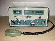
Description
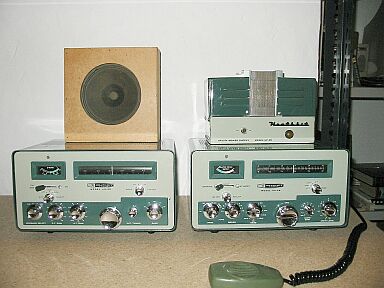
The HEATHK1T Model HX-20 Mobile Single sideband Transmitter is designed principally for mobile single sideband operation and is a
companion unit for the Model HR-20 Mobile Receiver.
It adapts equally well to fixed station operation, either as a transmitter or as an exciter for a high-power linear
amplifier such as the HEATHKIT Model HA-10.
Power levels up to 50 watts output are obtained on all bands, 80 through 10 meters. Heterodyne conversion circuitry and a temperature compensated VFO are employed for maximum frequency stability. The 80, 40, 20, 15 meter bands and 1.5 mc of the 10 meter band are covered
in seven 500 kc segments.
A VFO tuning knob with a 22 to 1 gear ratio and a slide-rule scale are used for tuning convenience and excellent “resetability.” Spring loading holds backlash to a
minimum.
Fixed 50 to 75 ohm loading is employed using a pi network output to suppress harmonic
radiation.
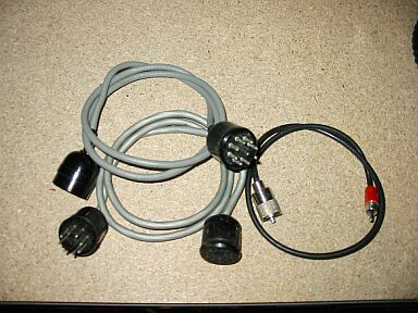
Rear panel connectors are provided for : -
RF output to the antenna;
receiver connections to the antenna;
receiver muting;
external relay connections;
CW keying jack;
external cut off bias.
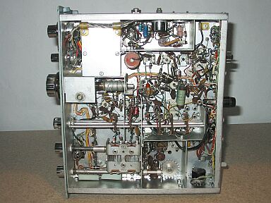
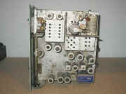
Thirteen tubes are used in the Transmitter, including two voltage regulator tubes; one for VFO voltage regulation and one for bias voltage regulation for the final
amplifier. Germanium diodes are used for the ALC
circuit and the balanced modulator circuit. Silicon diodes are used for the VOX and anti-trip circuits.
|
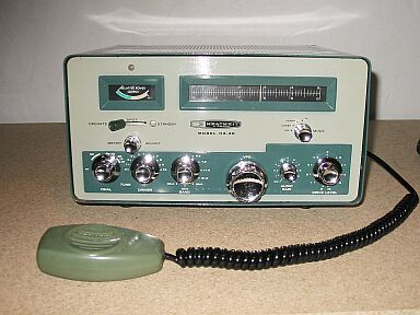
HX-20 Transmitter
|
|
Manual
with Circuit
Component Values &
Alignment
Details Below
As a Download
Click Here
|
Specifications
Types of Emission.
CW and SSB (upper and lower single sideband).
Power Input.
100 watts CW, 100 watts P.E.P. Single Sideband.
Output Impedance.
50 to 75 ohms with not more than 2 to 1 standing wave ratio.
Carrier Suppression
50 db below peak output.
Sideband Suppression
55 db below peak output.
Band Coverage
80 meter band 3.5 to 4 megacycles.
40 meter band 7 to 7.5 megacycles.
20 meter band 14.0 to 14.5 megacycles.
15 meter band 21.0 to 21.5 megacycles.
10 meter band A - 28.0 to 28.5 megacycles.
10 meter band B - 28.5 to 29.0 megacycles.
10 meter band C - 29.0 to 29.5 megacycles.
Frequency Stability
500 cps warm up 100 cps overall stability after warm up.
Keying
Grid block keying of 3rd mixer and driver stages.
Audio Input
High Impedance microphone.
Audio Frequency Response
400 to 3000 cps nominal.
ALC
Automatic level control voltage applied to IF amplifier stage.
Oscillators
All oscillators (except VFO) are crystal controlled.
All crystals are furnished.
Indicating Devices
Relative power output meter.
Front Panel Controls
Operate spot standby switch
Meter Adjust
Mode switch
Final Tune
Driver Tune
Band switch
VFO tuning
Audio Gain
Drive Level
|
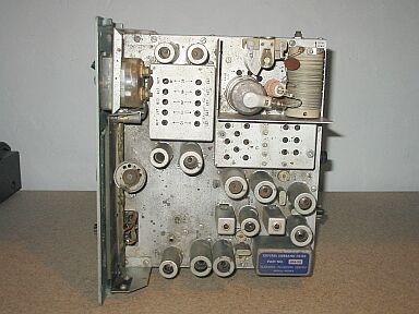
HX-20 Transmitter
|
|
HX-20 Transmitter
|
|
Manual
with Circuit
Component Values &
Alignment
Details Below
As a Download
Click Here
|
The Manual Consists
of the Following
Specifications.
Introduction.
Circuit Description.
Construction Notes.
Parts List.
Proper Soldering Techniques.
Step- By-Step Procedure.
Step- By-Step Assembly.
Initial Test.
Adjustment.
Alignment.
Installation.
Accessory Equipment.
Operation.
In Case of Difficulty.
Troubleshooting Chart (General).
Service Information.
Circuit Diagram with Component Values
This Version of the Manual
was supplied with factory built Units.
It does not contain full construction details.
There are no Layouts
|
|
|
Manual
with Circuit
Component Values &
Alignment
Details Below
As a Download
Click Here
|
Heathkit Mobile Transmitter HX-20
HX20
Manuals are Available Worldwide as a Download.Condensed Manual
with Circuit 42 pages
Manual 42 A4 pages worldwide
( For all Payment Options )
( Please Click the Payment Links Below )
|
|
We do all we can to provide
the very best that is available for you.
But in the unlikely event that any data should not be as you expected.
A refund is always available. Kind Regards Allen and Alanna. |
|