|
Marconi Frequency
Counter TF2431
|
|
Circuit Diagram, Service
Manual, Service
Information, Schematic Diagrams and Manuals |
|
For Repairing, Restoration and
Servicing of Vintage and Modern Electronic Equipment |
|
Manual and
Circuit
available
Details Below
As a Download
Click Here
|
|
Circuits
& Manuals
Military,
Radio, TV,
Amateur & Marine
World Wide Service
For
Lists Click Here
|
|
Use R/H scroll Bar
More information
below
Radio's For Sale
Click Here
Military and
Broadcast
Radio Ads Click
Here |
|
Military Radio Home
Click
Here If no Index to the left
|
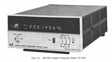
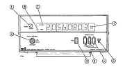
Marconi Frequency Counter
TF2431
1.1 INTRODUCTION
TF 2431 is a general purpose instrument suitable for measuring the frequency of signals in the band 10 Hz to 200 MHz.
Its versatile
input buffer and amplifier incorporating a. g. c. has high tolerance of signal distortion and noise and ensures reliable
operation over a wide dynamic range of input levels without the need for a manual control.
The counter has a bright 8-digit 7-segment 1. e. d. display with memory, automatic position
of a decimal point, leading zero suppression and active indication of overflow, hold and external standard operation.
Push button switches select the resolution required, the maximum being 0.1 Hz over the entire frequency range.
Gate times are derived from an internal 10 MHz crystal oscillator or from an external standard if required.
The high-stability alternative version of the instrument, Code No. 52431 - 302N, is fitted with an oven-controlled internal 10 MHz standard.
|
|
| The Manual contains the following
Chapter 1 GENERAL INFORMATION
1.1 Introduction
1.2 Data summary
1.3 Versions and accessories
Chapter 2 OPERATION
2.1 Installation
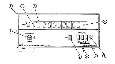
2.2 Controls and connectors
2.3 Frequency measurement
2.4 Use of external standard
2.5 Self check procedure
Chapter 3 TECHNICAL DESCRIPTION
3.1 Input amplifier gate and high speed decades
3.2 Clock selection and gate generator
3.3 Timing generator
3.4 Logic circuit
3.5 Switching
3.6 Display board
Chapter 4 MAINTENANCE
4.1 General
4.2 Fuses
4.3 Removing covers
4.4 Access to power supply
4.5 Adjustment of internal 10 MHz standard
4.6 Access to display board
4.7 Access to amplifier buffer
4.8 Power supply links
4.9 Power supply adjustment
4.10 Amplifier adjustment
4.11 AGC adjustment
4.12 Schmitt trigger adjustment
Chapter 5 Not assigned
Chapter 6 REPLACEABLE PARTS
Introduction and ordering
A0 Overall assembly
Al Function board
A2 : Display board
AlO Oscillator board
All : Oscillator board (high stability)
Miscellaneous mechanical parts
Accessories
Chapter 7 CIRCUIT DIAGRAMS
Circuit notes
Fig. 7.1 Interconnection diagram
Fig. 7.2 Function board
Fig. 7.3 Display board
Fig. 7.4 Oscillator boards
|

|
|
|
|
Manual and
Circuit
available
Details Below
As a Download
Click Here
|
Marconi Frequency
Counter TF2431
Manuals are Available Worldwide
as a Download.Manual including circuits £11.00 total of
36 pages
Manual 36 A4 pages worldwide
( For all Payment Options )
( Please Click the Payment Links Below )
|
|
We do all we can to provide
the very best that is available for you.
But in the unlikely event that any data should not be as you expected.
A refund is always available. Kind Regards Allen and Alanna. |
|