|
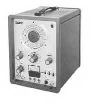
Philips Signal Generator PM5321 PM-5321
|
|
Circuit Diagram, Service
Manual, Service
Information, Schematic Diagrams and Manuals |
|
For Repairing, Restoration and
Servicing of Vintage and Modern Electronic Equipment |
|
Manual
with Circuits and
Layout images
Details Below
As a Download
Click Here
|
|
Circuits
& Manuals
Military,
Radio, TV,
Amateur & Marine
World Wide Service
For
Lists Click Here
|
|
Use R/H scroll Bar
More information
below
Radio's For Sale
Click Here
Military and
Broadcast
Radio Ads Click
Here |
|
Military Radio Home
Click
Here If no Index to the left
|
Philips Signal Generator PM5321 PM-5321
The PM 5321 signal generator
was designed for checking and adjusting A.M., F.M. and TV receivers in service workshops.
The frequency range comprises the A.M./F.M. broadcast bands and A.M./F.M./TV intermediate frequency ranges.
The output voltage can be modulated in amplitude over the
entire frequency range in the F.M. band and A.M./F.M.
intermediate frequency ranges, frequency modulation is also possible.
On account of the fact that the apparatus is also suitable for frequency modulation in the I.F. ranges, it lends itself very well for the visualisation of band-pass curves of I.F. amplifiers and I.F. filters on the screen of an oscilloscope.
As a result a receiver can be adjusted much faster than when use is made of the time-consuming system of measuring the
response curve point by point.
|
|
|
Manual
with Circuits and
Layout images
Details Below
As a Download
Click Here
|
The Manual Consists
of the Following
GENERAL PART
Introduction
Short description of the apparatus
Technical data
Accessories
DIRECTIONS FOR USE
Installation
Adjusting to the local mains voltage
Earthing
Switching on
Operation
Preliminary adjustment
Frequency
Amplitude
Modulation
Connecting the signal to the object under test
Application
The visualisation of band-pass curves
Adjustment of A.M. F.M. and TV-receivers
SERVICE DATA
Circuit description
R.F. oscillator
Amplitude modulation
Frequency modulation
A.M. and F.M.
Horizontal deflection voltages for an oscilloscope
1-kc/s oscillator
Blanking
Stabilised power supply
Impedance transformer PM 9532 B
Dummy aerial 4822 210 70023
Maintenance
Segment switches
Cabinet panels
Gaining access to and replacing parts
Removing the cabinet panels
Removing the knobs
Replacing the thermal fuse
Removing the front panel
Fitting a new driving cord
Removing the screening plates on the tuning tank
Replacing tuning capacitor Cl
Fault finding
General
Voltages
Faults that may occur
Checking and adjusting
Survey
Mains supply
Adjustment of the meter
Adjustment of the frequency ranges
F.M. 50 c/s
Amplitude modulation
R.F. voltage
Measurement of the frequency sweep
List of parts
Mechanical
Electrical
List of parts of the impedance transformer PM 9532 B
List of parts of the dummy aerial 4822 210 70023
List of parts of the measuring cable
List of Figures
Block diagram
Rear view
Functions of the controls and sockets
Diagram of the dummy 4822 210 70023
Displaying band-pass curves
Generating frequency markers
Mixing circuit
Low-pass filter
Mixing product
Marking pulse
Connecting the a.c. voltage meter to a receiver with a low
output impedance
Connecting the a.c. voltage meter to a receiver with a high
output impedance
Static adjustment of an A.M. receiver
Dynamic check of the I.F. band-pass curve
I.F. curve of an A.M. receiver
Adjustment of the F.M. discriminator
Adjustment of the I.F. circuits
Alternately damping and adjusting the primary and
secondary circuits
Dynamic adjustment of an F.M. receiver
Frequency scale
I.F. curve during the adjustment
I.F. curve in two stages of adjustment
Discriminator curve
Connection for adjusting the R.F. and oscillator circuits
Band-pass curve of the I.F. amplifier of a TV receiver
Connection of the various instruments to a TV receiver
Impedance transformer PM 9532 B
Equivalent circuit of the impedance transformer
Dummy aerial
Removing the knobs
Scale drive
Measuring set-up for checking the frequency sweep
Front view; indication of parts
Right-hand side-view; indication of parts
Left-hand side-view; indication of parts
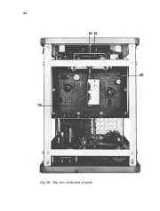
Top view; indication of parts
Rear view; indication of parts
Rear view; indication of parts
Measuring cable
Impedance transformer
Print A; tuning unit
Print B; R.F. Unit
Print C; modulator unit, side of parts
Print C; modulator unit, side of tracks
Print; supply part, side of parts
Print; supply part, side of tracks
Circuit diagram
|
Manual
with Circuits and
Layout images
Details Below
As a Download
Click Here
|
|
|
|
Manual
with Circuits and
Layout images
Details Below
As a Download
Click Here
|
Philips PM5321 PM-5321Signal
Generator
Manuals are Available Worldwide as a
Download.Manual
with
Circuits and Layout images 78 pages
Manual
78 A4 pages worldwide
( For all Payment Options )
( Please Click the Payment Links Below )
|
|
We do all we can to provide
the very best that is available for you.
But in the unlikely event that any data should not be as you expected.
A refund is always available. Kind Regards Allen and Alanna. |
|