|
R209 Mk2 MkII Mk11 Receiver
Reception Set Mk 2 Mk II Mk 11 Mark 2
|
|
Circuit Diagram, Service
Manual, Service
Information, Schematic Diagrams and Manuals |
|
For Repairing, Restoration and
Servicing of Vintage and Modern Electronic Equipment |
|
Manual and
Circuit
available
Details Below
As a Download
Click Here
|
|
Circuits
& Manuals
Military,
Radio, TV,
Amateur & Marine
World Wide Service
For
Lists Click Here
|
|
Use R/H scroll Bar
More information
below
Radio's For Sale
Click Here
Military and
Broadcast
Radio Ads Click
Here |
|
Military Radio Home
Click
Here If no Index to the left
|
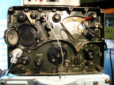
Reception set R209 Mk2
The Reception set R209 Mk2 was a 10
valve high grade super heterodyne receiver, with facilities for
receiving Voice (AM or FM) and CW.
The FM facility however was not required for operational use, CFS facilities were also provided.
It was
hermetically sealed, built on miniature lines and incorporated its own
vibrator power supply unit driven by a 12 volt battery.
The set could
have been used in the following stations : -
a) Auxiliary station to
replace the reception set R109 in the WS76 station.
b) Auxiliary station
to replace reception set R107 in the WS53 station.
c) Man - pack station.
d) Vehicle/animal station.
It could also be used in place of the reception
set R106 and R206 in cases where lightness was of paramount importance.
|
|
Ten valves and a neon stabilizer were
employed in the set, which attained high stability by means of a very
rigid RF chassis and well constructed condenser drive.
Other
features of the set included a unit system of construction and employment
of miniature technique throughout.
Frequency Coverage
1 to
20 Mc/s in 4 Bands.
Band1 : - 20 to 12 Mc/s.
Band 2 : -
12.5 to 5.5 Mc/s.
Band 3 : - 5.6 to 2.3 Mc/s.
Band 4 : - 2.3 to
1.0 Mc/s.
The set provided for reception from rod, open-wire or dipole
aerials, with loudspeaker and phone output.
Brief Electrical
Description
The two aerial inputs fed in at 80 ohm and 1000 ohm to
the RF amplifier.
A separate local oscillator was employed and this, with
the mixer and RF amplifier was mounted on the chassis.
|
|
Three IF units and the discriminator
unit were plugged into the IF chassis to which 460 kc/s output from the
mixer was fed.
A band -width of 5 kc/s at 6db was obtained in the IF
amplifier.
The limiter-discriminator unit employed a diode-pentode valve,
which was also used as a detector on AM.
The beat oscillator, also a
plug-in unit, was supported by the audio chassis.
The output was a
self-driven push-pull stage, fed into a loudspeaker and two pairs of
phones.
AVC on AM was obtained from the detector diode load and was
applied to the RF amplifier and to the 1st and 2nd IF amplifiers.
|
Manual and
Circuit
available
Details Below
As a Download
Click
Here |
There were three versions of the R209
all were general purpose portable HF receivers, with the same
frequency coverage of.
1 to 20 M/c/s with CW, AM, FM
and R/T.
R209Mk1
Powered from 6V DC.
A replacement for R107/109.
R209Mk2
Powered from 12V DC.
R209 Mk/2/B
(as picture) has a
DC/AC mains power supply operating from 12 or 24V DC and AC mains. |
|
The R209 Mk2 receiver
I have a
57 page manual
Electrical and Mechanical Engineering Regulations, it includes all Circuits Layouts Component lists etc.
57 A4 Pages containing the following
Prices below
General Description
Electrical Description
Mechanical Description
Hermetic Sealing
Controls
Technical Description
Aerial Input
RF Amplifier
Mixer
Local Oscillator
IF Amplifier
Detector
Discriminator
Beat Oscillator
AVC
Output Stage
CW Filter
Crash Limiter
Power Supplies
Component List
List of Figures
Block Diagram
Front Panel Layout
Simplified Discriminator Circuit
Audio Filter
Circuit Diagram
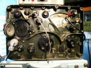
Layout Top and Bottom
Layout IF can
Layout Discriminator
Layout BFO
Layout PSU
Layout and Circuit Diagram Crash Limiter
It is comprehensive and gives all the relevant information to renovate a R209 Mk2 Receiver.
I used this manual to renovate my R209 Mk2.
|
R209 Mk2 MkII Mk11 Receiver
Reception Set Mk 2 Mk II Mk 11 Mark 2
Manuals are Available Worldwide as a
Download.
Manual 57 A4 pages worldwide
( For all Payment Options )
( Please Click the Payment Links Below )
|
|
We do all we can to provide
the very best that is available for you.
But in the unlikely event that any data should not be as you expected.
A refund is always available. Kind Regards Allen and Alanna. |
|