| Racal RA17 RA17L and
RA17C-12 Receiver 1.1 GENERAL DESCRIPTION
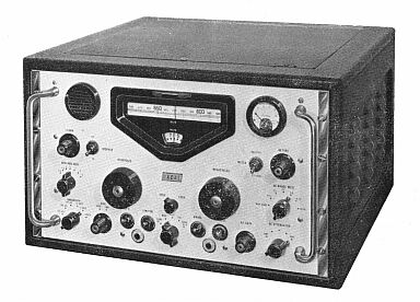
The Communications Receiver Type RA.17 has been designed for use as a general purpose receiver which will
provide a high order of sensitivity, selectivity and stability.
The receiver covers a frequency range from 1.0 to
30.0 Mc/s and extending, with slightly degraded performance, down to 500 kc/s.
A built-in crystal-controlled calibrator provides reference signals at each 100 kc/s division to permit exact alignment of the scale pointer.
Two independent i.f. outputs in parallel at 100 kc/s are provided for external use if required.
A number of audio outputs are available providing flexibility during operation; a small loudspeaker is fitted for monitoring purposes.
The receiver is designed to operate from 100-125 volts and 200-250 volts, 45
- 65 c/s mains supply.
The power consumption is approximately 100 watts.
1.2 NORTH AMERICAN VERSION
North American versions of the RA.17 receiver are identical to the Standard model but include
minor variations
in detail to comply with North American practice.
Certain tubes are changed to ensure that the set employs types commercially available in North America; this entails slight circuit changes to allow for differences in the tube operating voltages.
The level meter circuits are modified to include a calibrated “S” meter range.
The a.f. output stage is modified to give a maximum output of
1 watt.
Coaxial connections are changed from British to North
American standards and the supply connection comprises a lead directly connected to the set in place of the fixed plug and free socket fitted to the British version.
These instructions cover both types of receiver, where applicable attention is drawn to the differences between the two versions.
1.3 CONSTRUCTIONAL DETAILS
The receiver is designed for both bench (table) and rack mounting.
The
(The front panel is painted Light Battleship Grey (British Standard Specification 381C, colour 697) and has been carefully designed to minimise operator fatigue.
The dimensions of the front panel conform with the requirements for mounting in a standard 19-in. rack.
For bench mounting, the receiver is fitted in a robust steel cabinet, which has a rear opening to enable the operator to gain
easy access to the power input socket (Standard version only), the fuses and the termination strips.
A dust cover is provided with both models, this may be removed from cabinet-mounted receivers in conditions of high
ambient temperature.
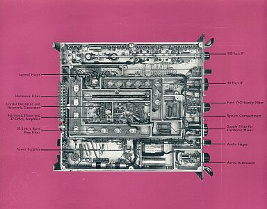
The chassis and major modules are of cast construction thus ensuring maximum rigidity and effective electrical screening.
Each receiver is supplied with three keys to facilitate removal of the control knobs, a plastic trimming tool and free coaxial terminations for aerial and i.f. connections.
Extra sleeves are provided with the terminations for alternative coaxial cable sizes.
TECHNICAL SPECIFICATION
Frequency Range 1—30 Mc/s. Range extends to
0.5 Mc/s with slight degradation of performance.
Stability
The average receiver, after warm-up time of 1 to 2 hours, will remain tuned to within 50 c/s of the
selected frequency under conditions of constant supply voltage and ambient temperature.
Input Impedance
75 ohms unbalanced.
Tuning
Effective scale length of approximately 145 feet, i.e. about 6 inches of scale length corresponds to 100 kc/s. Frequency increments remain substantially constant over the
entire range.
Calibration
A 100 kc/s signal derived from a 1 Mc/s crystal oscillator having an accuracy of 5 Parts in 10
to the 4 provides check points at 100 kc/s intervals.
Sensitivity
Al reception, bandwidth 3 kc/s:
1 micro V for 18dB signal-to-noise ratio.
Al reception, 30% modulated, bandwidth 3 kc/s;
3pV for 18dB signal-to-noise ratio.
Intermodulation
More than 100dB down for interfering signals at least 10% removed from the wanted signal.
Cross Modulation
For wanted signal levels between 3micro.V and
1mv, an interfering signal 10 kc/s removed and modulated 30% must have a level greater than 50dB above that of the wanted signal to produce a cross modulation of
3%. The ratio of wanted to unwanted signal is improved up to 10% off tune, at the rate of
3db per cent.
Blocking
With similar conditions to those for cross modulation, an unwanted signal f2
must be 60dB greater before the audio output of the wanted signal f1 is reduced by
3dB due to blocking.
Selectivity
Six alternative i.f. bandwidths are obtained by means of a selector switch. Filter details are:
-6dB
-66dB
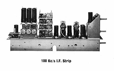
100 kc/s I.F. Output Detected Output
1. 13 kc/s
35 kc/c
28 kcls
2. 6-5 kc/s
22 kc/s
20 kc/s
3. 30 kc/s
15 kc/s
15 kc/s
4. 1-2 kc/s
8 kc/s
8 kc/s
5. 0.3 kc/s
Less than 2 kc/s Less than 2 kc/s
6. 0.10 kc/s
Less than 1.5 kc/s Less than 1.5 kc/s
Bandwidths 5 and 6 are obtained with crystal-lattice filters; differences in centre
frequencies of these bandwidth settings do not exceed 50 c/s.
LF. Output
100 kc/s at 75 ohm impedance. Level 0.2V approx. with a.v.c. in operation. Two outlets in parallel are provided.
Image and Spurious Responses
With wideband or tuned input, external image signals are at least 60dB
down. Internally generated spurious responses are below noise level in all cases.
Noise Factor
Better than 7dB throughout entire range.
B.F.O. Range
±8 kc/s.
B.F.O. Stability
With constant ambient temperature and supply voltage, drift after warm-up time of
1 to 2 hours does not exceed 50 c/s. For input level variations from 10
micro V to lmV, b.f.o. drift is negligible.
Automatic Volume Control
A.V.C. is applied to the r.f. and the final i.f. stages. An increase in signal level of 20dB above
1 microV improves the signal-to-noise ratio by 18dB. An increase in signal
level of 100 dB above l micro V increases the a.f output by less than 7dB.
A.V.C. Time Constants
Short: Charge—25 milliseconds.
Discharge—200 milliseconds.
Long: Charge—200 milliseconds. Discharge.—1 second.
A.F. Response
With 13 kc/s bandwidth, response remains within + or
- 4dB from 250 c/s to 6000 c/s.
A.F. Output
1. 2 1/4—in, loudspeaker (50mW) (1W, North American version) on front panel (switched).
2. Two headphone sockets in parallel on front panel. (See Note).
3. Three independent outputs of 3mW at 600 ohms at rear of chassis.
4. One output of 10mW at 600 ohms. Preset level is independent of A.F. GAIN control setting.
5. One output of 50mW (1W, North American version) at 3 ohms.
Note: The two headphone sockets are connected across the loudspeaker on the British
version and across one of the 600 ohm 3mW outlets on the North American version
of the receiver.
Distortion
Not greater than 5% at 50mW output. (1W, North American version)
Hum Level
With A.F. GAIN control at maximum, the hum level is never worse than 40dB below rated output (50mW or 1W respectively).
Noise Limiter
A series noise limiter circuit can be switched into operation to provide limiting at modulation levels exceeding 30%.
Meter Indication
Alternative switching for indication of signal carrier level or
a.f. output level. An S meter is incorporated in the North American version of the receiver.
Power Supply
100 -125V and 200 - 250V, 45—65 c/s. Power consumption 100W approx.
Weight
Rack mounted 67 lb. (30.5 kg).
In cabinet 97 lb. (44 kg.)
|
|