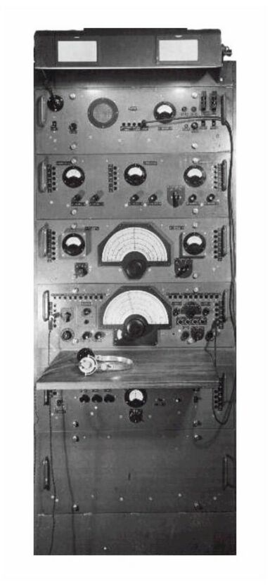
| Reception Set R201
Radio
Receiver
Purpose and facilities
The purpose of this receiver is the maintenance of long-distance
high-speed telegraphy communication services with minimum requirements of
personnel at the receiving end.
Long-distance communication implies the use of indirect paths of
propagation with consequent troubles arising from : -
(a) The arrival of signals along more than one path.
(b) The fading in strength of signals due to irregular reflection or refraction at ionised layers.
(c) The variation in angle of arrival due to variations in these layers.
2. To combat the above troubles full use is made of automatic gain control and three
widely spaced directional aerial systems.
When one system is receiving a strong signal the
other two may be receiving relatively weak signals.
As three distinct R.F. and I.F. channels are used, connected one to each of the three aerials, the system with the strongest signal will take control by means of the common
A.G.C. line and quiteten the other two.
3. Frequency drift is regulated by a system of automatic frequency control (A.F.C.) on the receiver
which automatically retunes the local oscillator unit whenever the beat note drifts by more than about 120
c/s.
This facility will work only on C.W. reception.
4. The receiver is designed principally for use on telegraphy (CW)
and is so designed that it requires only occasional attention from the staff. Diversity reception on
keyed carrier M.C.W. is also possible, using the. B.F.O. on the receiver,
as on C.W.
Range
5. This receiver is used for world wide reception
BRIEF ELECTRICAL DESCRIPTION
Receiving aerials
6. The receiver is used with three spaced directional aerial systems, such as rhombics, connected to the receiver through
75 ohm coaxial transmission lines.
The design of the aerial system depends on the nature of the service to be operated.
Receiver circuit
7. The receiver comprises three superheterodyne channels feeding a common L.F. amplifier.
The three inputs from the aerials are taken to three R.F. and frequency
changer chassis, each containing two R.F. amplifying stages and a mixer valve.
These chassis, together with the oscillator multiplier chassis, which provides frequency multiplication for the single local oscillator, are all incorporated in the R.F. unit.
8. The output of the mixers is fed into three identical I.F. chassis (together forming the I.F. unit).
Each chassis incorporats a crystal filter, three I.F. amplifying stages, an A.G.C. I.F. amplifying stage, an L.F. amplifier and band-pass filter, two pairs of rectifiers for speech, bridge, L.F. and A.G.C. circuits and a meter valve.
9. The outputs of the rectifiers on the three I.F. chassis combine and feed the common L.F. unit.
This incorporates a heterodyne oscillator optically crystal controlled or manually tuned, to provide an L.F. beat note for C.W. working.
Filters and an L.F. amplifier for feeding the monitoring loudspeaker and the speech line; filters and amplifiers for feeding the C.W. line and bridge unit and for
operating the automatic frequency control (A.F.C.) circuits and a muting valve.
The discriminator valves of the A.F.C. circuit feed D.C. amplifiers which operate motor control relays.
The motor, which is controlled by these relays, drives a trimmer condenser connected across the tuned circuit of the master oscillator which is housed in the L.F. unit.
The A.G.C. load resistance, delay and adjustable time constant circuit, is also included in the L.F. chassis.
Two alternative inputs are available for the bridge unit, either A.C. from the C.W. line L.F. amplifier or D.C. direct from the L.F. rectifiers. Both inputs can be subject to automatic muting.
The bridge unit comprises a V.F. bridge for operating a recorder and a tone sender for connection to a tone line.
|
|