|
TCS 12 TCS12 Transmitter 52245 Receiver
46159
TCS 1 2 3 4 5 6 7 8 9 10 11 12 13 14
TCS1 TCS2 TCS3 TCS4 TCS5
TCS6 TCS7 TCS8 TCS9
TCS10 TCS11 TCS12 TCS13 TCS14
Collins Radio Hamilton Radio Download
|
|
Circuit Diagram, Service
Manual, Service
Information, Schematic Diagrams and Manuals |
|
For Repairing, Restoration and
Servicing of Vintage and Modern Electronic Equipment |
|
Manual and
Circuit
Plus Additional Articles
available
Details Below
As a Download
Worldwide Service
Click Here
|
|
Circuits
& Manuals
Military,
Radio, TV,
Amateur & Marine
World Wide Service
For
Lists Click Here
|
|
Use R/H scroll Bar
More information
below
Radio's For Sale
Click Here
Military and
Broadcast
Radio Ads Click
Here |
|
Military Radio Home
Click
Here If no Index to the left
|
|
TCS 12 TCS12 Transmitter 52245 Receiver
46159 TCS 1 2 3 4 5 6 7 8 9 10 11 12 13 14
TCS1 TCS2 TCS3 TCS4 TCS5 TCS6 TCS7 TCS8 TCS9 TCS10 TCS11 TCS12 TCS13 TCS14 |
TCS 12 TCS12 Transmitter 52245 Receiver
46159
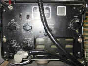
The TCS series of transmitters and
receivers were designed and originally built for the US Navy by the
American Collins Company, though later several other manufactures also
built them.
The series was numbered consecutively TCS1 to TCS14. The US Navy
numbered them COL-52245 for the transmitter and
COL-46159 for the receiver.
The numbers prefixing the Navy number is a
code denoting the manufacturer, eg COL Collins CHI Hamilton.
They were supplied to the US Navy for duties
similar to the British W/S19, e.g. / P and / M from tanks, trucks
and similar vehicles.
The TCS was also used as an emergency radio aboard
merchant ships.
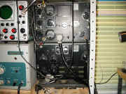
Although intended to work as a single inter-connected
unit, the transmitter and receiver are in fact physically
separate.
|
|
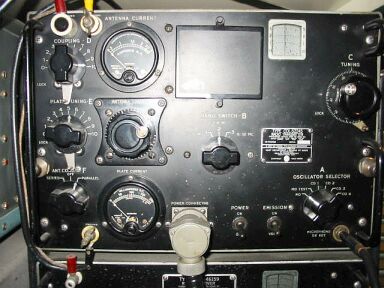
| Transmitter 52245
The
transmitter consists of a VFO / Buffer - Doubler / PA with an integral
push-pull modulator, there is provision for four switched crystals as an
alternative to the VFO.
Frequency
Coverage
1.5 to12.0 Mc/s in 3 bands.
Band 1 : - 1.5 to 3.0
Mc/s.
Band 2 : - 3.0 to 6.0 Mc/s.
Band 3 : - 6.0 to 12.0 Mc/s.
When used in conjunction with its receiver the TCS transmitter has full
"push-to-talk" or "break-in" facilities.
Power
Supply
The power requirements for the transmitter are : -
HT (1)
400 volts DC at 200 mA
HT (2) 220 volts DC at 40 mA
LT12 volts AC/DC at
2.5 amps
Relay supply 12 volts DC at 1 amp. |
|
The Transmitter runs approx 35 watts
input on phone and 80 watts on CW.
The Modulator
The TCS had an incorporated modulator, it consists of a pair of 1625's
operating in class B push-pull, modulating the PA on plate and screen via
the transformer.
There is no pre-amplifier, the 1625's being driven direct
from the microphone transformer, which is designed to work with a
carbon-button microphone of about 100 ohms.
Auto-bias and the energizing
voltage for the microphone develops across a resistor.
The "Emission
Selector" switch cuts the heater volts from the parallel PA valve
when placed in the "Voice" position, it also switches on the
heaters of the two modulator valves .
|
|
It also places the modulator valves on
the HT rail via a relay contact, though no HT will be available until
the push-to-talk switch is closed and the relay applies the HT.
When the
transmitter is switched to the CW condition, the modulator valves have
neither HT nor heater volts applied, it follows therefore that when
changing from one function to another, time must be allowed for the
heaters to warm up.
All supplies to the transmitter are fed through a
16-pin Cannon plug.
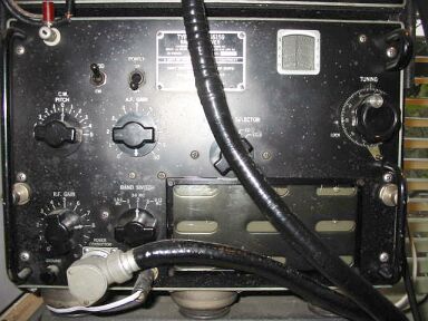
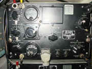
Receiver 46159
This is the companion
receiver to the transmitter mentioned above, the Frequency range is
identical.
The size, panel layout and construction are very similar to the transmitter
(52245).
|
Full Manuals with
Circuits available
Details Below
TCS Full Manual
Transmitter and Receiver
Click
Here
TCS Additional Articles
Click
Here TCS Receiver Faults
Click Here |
The Receiver 46159 is a conventional seven valve superhet, the valve
run is as follows
RF,12SK7
Mixer, 12SA7
Osc., 12A6
1st IF, 12SK7
2nd
IF,12SK7
Det / BFO, 12SQ7
Audio, 12A6.
The IF is 455 kc/s, it will be
seen from this that the receiver has a separate oscillator valve.
On the
front panel will be found a switch marked "Oscillator Selector"
and one of four crystals can be used as an alternative to the IF
oscillator.
The crystals are ground to be 455 kc/s above the signal
frequency (it spot tunes the receiver).
Other controls on the front panel
are : -
HT on /off
BFO on /off
CW pitch
RF gain /AVC on/off
LF gain
Band-switch and the main tuning control.
|
Full Manuals with
Circuits available
Details Below
TCS Full Manual
Transmitter and Receiver
Click
Here
TCS Additional Articles
Click
Here TCS Receiver Faults
Click Here |
When the BFO is on, the AVC is
inoperative.
The power and control circuits from the transmitter arrive
via a twelve-pin Cannon plug, Type GK-12-23.5 AC.
Though designed to work
in conjunction with the TCS transmitter(52245),
the receiver with the exception of the power
supply is self contained.
The receiver is muted during transmission by
cutting off the HT to the screens of the RF and IF valves.
A relay in the
transmitter switches the HT from the exciter to the receiver screens when
the push-to talk switch, or the CW key is open.
The relay rests in the
receive position.
Modulation
The carbon button microphone will
modulate the transmitter to about 80%. |
|
| So much for the two major units
of the TCS equipment, apart from the Rx / Tx as described, there were
several power supplies made for the series.
These are rather rare
(particularly the 230v AC mains unit). |
|
- TCS Auxiliary Equipment US Navy No
416T-3 Dynamotor 12v DC
input 21770
- 416T-4 Dynamotor 12v DC
input 211035
- 416T-4 Dynamotor
12v DC input 21881
- Motor
Generator 24v DC input 21826
- Motor
Generator 32v DC input 21775
- Motor Generator 115v
DC input 21776
- Motor Generator 115v
AC input 21777
- Motor Generator 230v
DC input 21827
- Rectifier
Unit 115v
AC input 20218
- Rectifier
Unit 230v
AC input 20242
|
Full Manuals with
Circuits available
Details Below
TCS Full Manual
Transmitter and Receiver
Click
Here
TCS Additional Articles
Click
Here TCS Receiver Faults
Click Here |
|
TCS Receiver
Faults
My TCS Receiver had been stored for years unused, I replaced the following components I think for crackling noises, it was a while ago.
C205 100pf
C218 50pf
C220 100pf
C230 500pf
C229 I reduced it to 1000pf from 2000pf something to do with the BFO pitch.
I also replaced the following resistors on the BFO just in case as it was intermittent.
R222 220k
R221 220k
R229 470k
The only modification I did was to add a 25mfd to the un-decoupled cathode of the audio output valve V207, to increase the volume.
It will now drive a speaker at good volume : )
Good Luck Allen G0RIT
|
|
List of Manufacturers By
Code Designation |
22A
Allen-Bradley Company
118 W. Greenfield Avenue
Milwaukee, Wisconsin.
84A
Arrow-Hart & Hegeman Co.,
108 Hawthorne Street
Hartford, Connecticut.
68B
Breeze Corp., Inc.
18 to 38 South Sixth Street
Newark, New Jersey.
97B
Bussmann Mfg. Company
2538 W. University St.,
St. Louis, Missouri.
10C
Cannon Electrical Devel. Co.,
420 W. Avenue 33
Los Angeles, California.
25C
Centralab, Inc.,
900 East Keefe
Milwaukee, Wisconsin.
30C
Central Screw Company
3511 Shields Avenue
Chicago, Illinois.
55C
Chicago Transformer Corp.,
3501 West Addison
Chicago, Illinois.
64C
Collins Radio Company
Cedar Rapids, Iowa.
65C
Communications Products, Inc.
245 Custer Avenue
Jersey City, New Jersey.
75C
Cornell-Dubilier Electric Corp.,
1000 Hamilton Blvd.,
South Plainfield, New Jersey.
96C
Cutler-Hammer
1333 West St. Paul Avenue
Milwaukee, Wisconsin.
60E
Eicor, Inc.,
1060 W. Adams Street
Chicago, Illinois.
70F
Fischer Special Mfg. Company
2729 Morgan Street
Cincinnati, Ohio.
|
25G
General Ceramics Company
30 Rockefeller Plaza
New York, New York.
40G
General Electric Company
Schenectady, New York.
85G
Guardian Electric Mfg. Co.,
1620-27 W. Walnut Street
Chicago, Illinois.
05H
Hammarlund Mfg. Company
424 W. 33rd Street
New York, New York.
80H
Harvey Hubbell, Inc.,
1930 Thomas Street
Bridgeport, Connecticut.
28J
International Resistance Co.,
1100 Terminal Commerce Bldg.,
Philadelphia, Pennsylvania.
35J
International Telephone Devel. Co., Inc.,
137 Varick Street
New York, New York.
42J
Isolantite Corporation
10 Park Place
New York, New York.
70J
Jensen Radio Mfg. Company
6601 5. Laramie Avenue
Chicago, Illinois.
77J
E. F. Johnson Company
Waseca, Minnesota.
42L
Leach Relay Company
5915 Avalon Street
Los Angeles, California.
78L
Littelfuse Laboratories
4765 Ravenswood Avenue
Chicago, Illinois.
90L
Lord Manufacturing Company
1639 W. 12th Street
Erie, Pennsylvania.
05N
National Company, Inc.,
Malden, Massachusetts.
25P
Ohmite Mfg. Company
4837 Flournoy Street
Chicago, Illinois. |
40P
Paper Products
DeWitt, Iowa.
65P
Pheoll Mfg. Company
5708 Roosevelt Road
Chicago, Illinois.
96R
Russell Electric Company
340 W. Huron
Chicago, Illinois.
02S
Sangamo Electric Co.,
1935 Funk Street
Springfield, Illinois.
l0S
Shakeproof Lock Washer Co.,
2573 N. Keeler Avenue
Chicago, Illinois.
42S
Signal Electric Mfg. Company
1939 Troam Street
Menominee, Michigan.
50S
Simplex Wire & Cable Co.,
79 Sidney Street
Cambridge, Massachusetts.
64S
Solar Manufacturing Corporation
Bayonne, New Jersey.
65S
Speer Resistor Corporation
St. Mary’s, Pennsylvania.
l0T
Telephonics, Corporation
350 W. 31st Street
New York, New York.
20T
Thordarson Electric Mfg. Company
Huron & Kingsbury Streets
Chicago, Illinois.
45W
Weston Electrical Inst. Corp.
619 Frelinghuysen Ave.
Newark, New Jersey.
95W
Wrought Washer Manufacturing Co..,
2105 South Bay Street
Milwaukee, Wisconsin.
50X
X-L Radio Laboratories
420 W. Chicago Avenue
Chicago, Illinois.
|
|
Connectors for the TCS Series and
other radios are available at a price from the company below.
This information was kindly
forwarded by Mr. Michael Starke
Hello Allen,
In the UK these plugs are being sold by PEI-Genesis, www.peigenesis.com
You want to contact Duncan Loveridge, duncan.loveridge@peigenesis.com
Phone: 08707-202 560
The connectors are available in two basic versions straight and angled.
In addition to that you can have them in 2 variations for the cable
thickness 1/2" & 5/8".
The cheapest is BPS 35.94 for the straight 5/8 version angled this is BPS 46.95
For the 1/2" version you will have to pay in an angled design BPS 51.16. and BPS 37.11 for the straight version.
Regards to Alanna,- my wife is not quite different, but we are not discussions shoes here nor the number of radios a man needs....
Best regards.
Michael Starke
Germany
Update By Michael
As for the power-plug for the TCS units I found another source:
www.fairradio.com
Price: $25.00 plus $10.00 shipping cost. |
The TCS Transmitter
and Receiver Manual
I can supply a high quality scanned copy of the original Collins TCS manual
covering both the transmitter, receiver, various power supplies and cables etc.
The Transmitter and Receiver sections of the manual
are integrated, therefore
it is not possible to separate them.
The Manual
includes all the Circuit Diagrams in some 172 A4 pages, containing the following : -
Introduction
Index to Illustrations
Index to drawings
General Characteristics
Transmitter Characteristics
Receiver Characteristics
Power Supply Equipment
Accessories
Installation
Adjustments and Operation
Circuit Description
Maintenance and Service
Appendix
Typical Performance Data
Voltage Readings
List of Major Units
Parts List by Symbol Designation
Applicable Colour Codes
Illustrations
Valve Data
Drawings
Illustrations
Transmitter
Front
Top Open
Bottom Open
Left Side
Left End Casting Inside
Exciter Top and Bottom
Crystal Bracket Assembly Top and Bottom
Exciter Plate Tank Top
Front Panel Inside
Capacitor Assembly Front and End
Receiver
Front
Top
Bottom
Left End
Right End
Rear Open
RF Assembly Side
Converter Assembly Side
Oscillator Assembly Side
RF Chassis Top and Bottom
IF Bottom 3 Views
BFO Bottom View
Various Power Units 14 Views
Remote Control Top and Rear Open
Loading Coil Front Closed Front Open
Index of Drawings
Block Diagram
Horizontal and Vertical Layout
Control Unit Layout
Various Power Unit Layouts 4
Transmitter Circuit Diagram
Receiver Circuit Diagram
Control Unit Circuit
Handset Circuit
Power Unit Circuits 4
Transmitter Power Cable Circuit
Receiver
Remote Control Cable Circuit
Loading Coil Connections
TX and RX Oscillator Circuits
Practical Wiring Diagrams 7
Master Oscillator Coil
TX Coil 2
Buffer Coil
Stator Coil
Rotor Coil
Variable Inductance Coil
Antenna Coil 3
Converter Coil 3
Oscillator Coil 3
It is very comprehensive and gives all the relevant information to renovate operate and maintain the TCS
Transmitter and Receiver.
|
|
Also Available
The TCS
Transmitter and Receiver
Additional Articles 33 pages. |
The TCS Transmitter Receiver Assembly Notes on Design Construction and
Amateur Band Applications.
Modifying the TCS Transmitter
Removal of
Power Connecter and Relays, Modified VFO Buffer Doubler HT Wiring, Keying
and Protective Bias for PA, Modulator Addition of Driver Stage.
Modifying the TCS Transmitter
Speech Pre -
Amplifier, TVI Factor, Operation and Results.
Two More Bands on the TCS
Modifications for
Twenty and Fifteen.
Some Modifications for the TCS Receiver
Fitting Band spread, Selectivity Improvements, Separate RF and IF Gain Controls, Valve
Changes.
Back Comes the TCS Some Useful References.
The Collins TCS Series Remembered
The
Transmitter, The Receiver, Servicing, Power Source Operation Debugging,
240 volt AC for the TCS TX RX ( Includes
circuit of home constructed power supply.
)
Valved Communications Receivers The Collins TCS
General Description, Circuit in Detail, External Power Supply Requirements,
If Alignment,
Radio Frequency Alignment, Suggested Modifications.
A home constructed Power Supply for the TCS
Transmitter and Receiver.
( It includes the suggested power supply circuit
diagram with Component Values. )
|
TCS Transmitter and
Receiver
Manuals are Available Worldwide as a
Download.
Cost of the Full Manual 172 pages covering the Transmitter, Receiver, various Power supplies and
Cables etc, including Circuit Diagrams.
Manual
172 pages worldwide
( For all Payment Options )
( Please Click the Payment Links Below ) |
Articles for the TCS Transmitter and
Receiver
Manuals are Available Worldwide as a
Download.
Articles 33 pages worldwide
( For all Payment Options )
( Please Click the Payment Links Below ) |
Special Offer Manual and Additional
Articles
Manuals are Available Worldwide as a
Download.
Total
205 Pages
( For all Payment Options )
( Please Click the Payment Links Below
|
|
We do all we can to provide
the very best that is available for you.
But in the unlikely event that any data should not be as you expected.
A refund is always available. Kind Regards Allen and Alanna. |
|
Manuals are Available
Worldwide as a Download
Thank you for your interest. Allen
and Alanna G0RIT
Should you wish to purchase
 For Worldwide Prices Payment Options and Delivery
Details
For Worldwide Prices Payment Options and Delivery
Details
Full Manual TCS Receiver and
Transmitter
including Circuit Diagrams 172 pages
For Worldwide Prices Payment Options and Delivery
Details
TCS
Articles 33 pages
For Worldwide Prices Payment Options and Delivery
Details
Special Offer Manual and Additional
Articles
TCS
Full Manual and Articles covering both the Transmitter and Receiver Total
205 Pages


|
|