| The Manual Contains the
Following :-
General description
Purpose and facilities
Weight and dimensions
Frequency range
Accuracy
Power supply
Construction
Technical description
The wavemeter circuit
The power supply circuits
The L.T. supply
The H.T. supply
Alternative H.T. supply
The tuning mechanism
The inductance.
The gearing and associated mechanism
The range switch
The scale plate
The correction chart
Working instructions
Preliminary
To set the wavemeter to a given, frequency
To set a sender to a given frequency
To set a receiver to a given frequency
To determine the frequency of a received signal
To determine the frequency on which a transmitter is operating
Use of a H.T. battery in place of the H.T. unit
Use of the white tablet on the front panel
Maintenance and repair
Maintenance of the wavemeter
The correction chart
Re-setting the trimming condensers
Repairs to the wavemeter
To remove the wavemeter from the case
To remove the front panel
Assembly
The H.T. unit (Units H.T., vibratory, No. 1)
To remove the unit from its case
To change the vibrator
Appendices
List of main components
Complete station
Crystal unit
General description
Technical description
Check points
Method of use
Miscellaneous uses
List of main components
Diagrams
Fig. 1. Wavemeter, Class C, No. 1—Circuit diagram
Fig. 2. Units H.T., vibratory, No. 1—Circuit diagram
Fig. 3. Wavemeter, Class C, No. 1—Simplified circuit
Fig, 4. Crystal unit—Circuit diagram
Plates
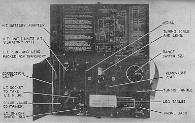
Wavemeter, Class C, No. 1—General view.
Wavemeter, Class C, No. 1—Internal view showing HT. plug dismantled.
Waveméter, Class C, No. 1—Internal view, top panel removed
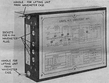
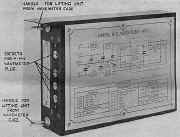
Units HT., vibratory, No. 1—External view
Units H.T., vibratory, No. 1—Internal view
|
|