|
Wireless Set No 18 Transceiver
WS
18 Transmitter Receiver
|
|
Circuit Diagram, Service
Manual, Service
Information, Schematic Diagrams and Manuals |
|
For Repairing, Restoration and
Servicing of Vintage and Modern Electronic Equipment |
|
Circuits Layouts and
Operation Instructions
Details Below
As a Download
Click Here
|
|
Circuits
& Manuals
Military,
Radio, TV,
Amateur & Marine
World Wide Service
For
Lists Click Here
|
|
Use R/H scroll Bar
More information
below
Radio's For Sale
Click Here
Military and
Broadcast
Radio Ads Click
Here |
|
Military Radio Home
Click
Here If no Index to the left
|
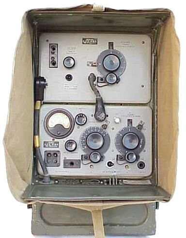
Wireless Set No 18 Transceiver WS
18 Transmitter Receiver
The
Wireless Set No.l8. was designed for short range telephony and CW. working in forward areas,
and was primarily intended for use between Battalion HQ and Company HQ.
It
could be used as a ground station for working in the open or from cover, and
as a man carried back set for working on the march.
The set is entirely self contained in one unit containing Sender, Receiver and Batteries.
FREQUENCY RANGE
The set covers a frequency band of 6 mc/s—9 mc/s (50 metres—33,3 metre.) in a single range.
This
band normally provides a minimum of about eighteen channels of
communication outside the Army band, ie above 7500 kc/s, and also gives an
overlap into the Army band to permit working with “wireless Sets No.1
and No. 11.
AERIALS
A sectional rod aerial is packed with the sat and may be erected on the
set to give a self-supporting aeria1 up to 10 feet high.
Other forms of aerial which may be used with the set are given below.
GROUND AERIAL
The ground aerial consists of a length of insulated wire connected to the
aerial of the set at one end and thrown out along the ground.
It is intended for working
from trenches and other forms of cover where a vertical rod aerial would be too conspicuous.
In certain circumstances the
ground aerial may he used as an elevated extension to the rod aerial.
HORIZONTAL HALF OR QUARTER WAVE AERIALS
For long range working half or quarter wave horizontal serials may be used.
They may be either end—fed
half or quarter wave aerials or “Wyndom” aerials.
For working into the Army band
i.e. below 7.5 mc/s and Aerial Horizontal End—Fed or an aerial Horizontal C. as used with “Wireless
Sets No.11, may be used.
THE CIRCUIT
The signal frequency of the sender is generated by a master oscillator circuit followed
by a single power amplifier.
The aerial is auto—coupled to the power amplifier by aerial
taps to a parallel tuned output circuit.
There are thus three tuning controls the ‘M.O. TUNING”, ‘AERIAL TUNING,’ and “AE
SWITCH.”
NETTING
By means of the netting ,device a group of “Wireless Sets No.18 may be tuned to One frequency
simultaneously, the frequency chosen being radiated in the first instance as a signal by a central control station.
Any set may than communicate with any other set in the group or with the control station.
Such a group is termed a’
net” and the process of tuning the sets in the net to a common frequency, “netting”.
The netting device used in the
Wireless Set No.18. consist. of a plunger switch by which the master oscillator
valve of the sender may be switched on while the set is in the receiving condition.’
When netting, the master oscillator frequency is adjusted so that a beat note is heard between the
master oscillator and the incoming signal.
“When the beat note is set to zero, the
frequency of the master oscillator is the same as that of the incoming signal.
MODULATION
Modulation takes place on the control grid of the power amplifier valve and is
set to give full modulation of the carrier at a normal loud voice level.
No adjustment
for depth of modulation is provided.
SEND RECEIVE SWITCH
Changing over from send ‘to receive is performed by the pressel switch of the
microphone.
There is no change—over switch on the panel of the set.
C.W. W0RKING’ MARK 2 AND 3
For the purpose of C.W. transmission a close—circuit jack is connected in the
H.T. supply to the P.A. valve and a Key is connected by means of Key and Plug
Assembly No. 8. for C.W. operation.
The above Key embodies the send—receive switch
and is connected to the filament supplies of sender and receiver.
|
|
|
Circuits Layouts and
Operation Instructions
Details Below
As a Download
Click Here
|
| The Information Consists
of the
Following :- General Description
Operation
Circuit Diagram
Transmitter
Circuit Diagram Receiver
Component list
Top And
Bottom Chassis
View Transmitter
Top and Bottom Chassis View Receiver There are no alignment instructions
|
Circuits Layouts and
Operation Instructions
Details Below
As a Download
Click Here
|
Wireless Set No 18 Transceiver WS
18 Transmitter Receiver
Manuals are Available Worldwide as a
Download.
Information consisting of 12 pages including the Circuit with Component
values
Manual
12 A4 pages worldwide
( For all Payment Options )
( Please Click the Payment Links Below |
|
We do all we can to provide
the very best that is available for you.
But in the unlikely event that any data should not be as you expected.
A refund is always available. Kind Regards Allen and Alanna. |
|